Environmental Engineering Reference
In-Depth Information
Main : 125 k
5 ms/div
V
dc
V
1
I
ac
V
2
Z1 : 12.5 k
500 us/div
Zoomed
V
dc
I
ac
V
1
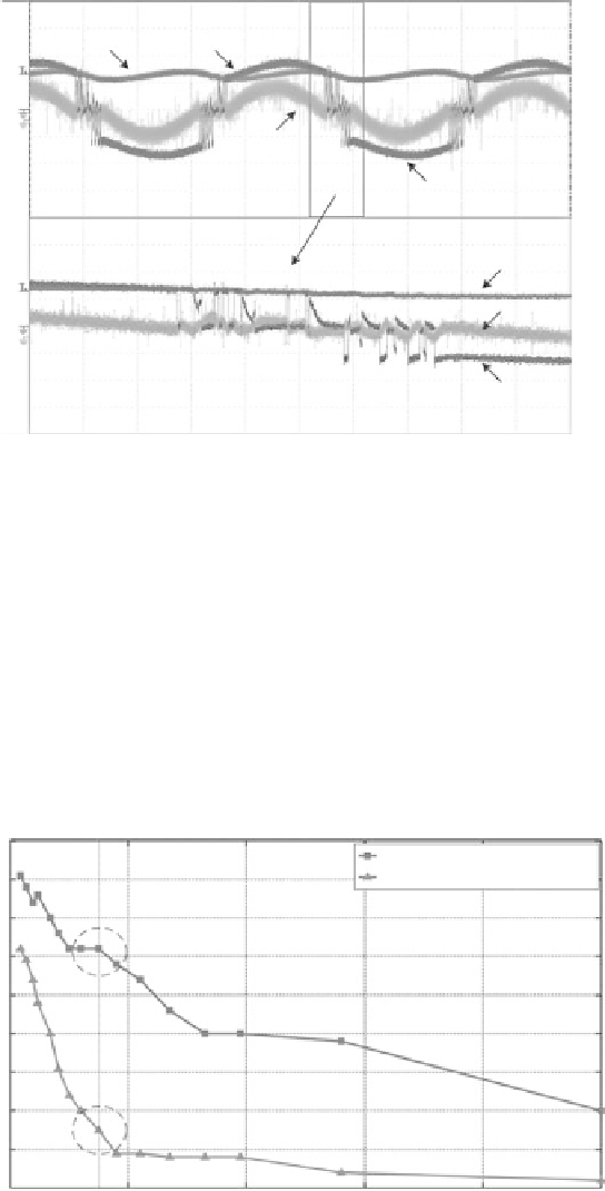
FIGURE 2.7
Experimental waveforms of an active MOSFET full-bridge rectifier using the proposed current
sense approach at an optimal load condition.
the passive rectifier, which allows the wind turbine to continue harvesting
even for very low incoming wind speeds. In addition, more electrical power
is harvested from the wind turbine (see
Figure 2.9
), thus, a higher AC-DC
power conversion efficiency is achieved over a wide range of wind speeds as
shown in
Figure 2.10
.
Consolidating the experimental data collected for both the passive and
active
rectifiers,
the
efficiencies
of
both
rectifiers
are
calculated
using
Vo ltage Drop across Two Diodes/MOSFETs (V) vs. Load Resistance (Ω)
0.9
Diode rectifier @3.62 m/s
MOSFET rectifier @3.62 m/s
0.8
0.7
0.6
0.5
0.4
0.3
0.2
0.1
0
0
150 200
400
Load Resistance (Ω)
600
800
1000
FIGURE 2.8
Voltage drop comparison between diodes and MOSFETs (V) over a range of load resistance (
).


Search WWH ::

Custom Search