Environmental Engineering Reference
In-Depth Information
1 and 50 MHz, the efficiency of the WPT system still remained at its optimal
for different coil radii between 5 and 100 cm. Take, for example, at operating
frequency of 100 kHz, it is observed from
Figure 6.17
that the efficiencies of the
WPT system with a coil radii of 5 and 100 cm were 60% and 95% respectively.
There was a significant difference in the system efficiency of around 35% when
the coil radius changed. As such, it is required to operate the WPT system
with a coil radius of 5 to 100 cm to be within 1 to 50 MHz so that maximum
power throughput is achieved.
6.2.2.3 Simulation of Efficiency versus Number of Turns
In this case, the number of turns in each coil were varied for 3, 5, and 7
turns to determine the behaviour of the WPT system efficiency over a range
of frequencies. According to
Equation 6.8
, it can be seen that the mutual
inductance
M
of the coils is a function of the square of
N
turns. As
N
increases,
it is expected that
M
increases and so does the coupling coefficient
, where
the relationship is illustrated in
Equation 6.7
. The simulated results are shown
in
Figure 6.18
.
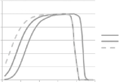
Like the previous case, it is observed in
Figure 6.18
that when the number
of turns changed from 3 to 7, the optimum efficiency band starts to shift
again towards the lower-frequency region. This is because of the change in
the ohmic and radiative resistances, as expressed in
Equations 6.10
and
6.11
,
respectively, as well as the coupling coefficient
, which ended up changing
the efficiency of the WPT system.
6.2.2.4 Simulation of Efficiency versus Distance
The mutual inductance of the coils, as expressed in
Equation 6.8
, is inversely
proportional to the cubic separation distance
D
between the coils. As the
Eciency vs. No. of Turns
120.00%
100.00%
80.00%
5 Turns
3 Turns
7 Turns
60.00%
40.00%
20.00%
0.00%
0.000001
0.0001
0.01
1
100
10000
Frequency (MHz)
FIGURE 6.18
Efficiency of a WPT system for different numbers of winding turns.


Search WWH ::

Custom Search