Environmental Engineering Reference
In-Depth Information
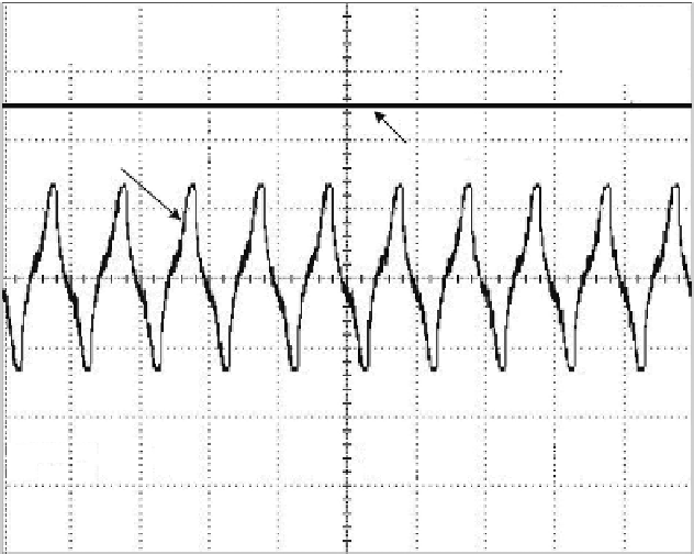
CH1 = 5 V
AC 1:1
CH2 = 5 V
DC 1:1
20 ms/div
(20 ms/div)
NORM:50 kS/s
(a) Output AC voltage of stray
magnetic energy harvester
(b) Output DC voltage
of voltage doubler
= Trace1 =
P-P
13.40 V
Rms
3.777 V
Freq
50.00 Hz
= Trace2 =
Max
12.80 V
Min
12.40 V
Avg
12.55 V
FIGURE 6.11
Waveforms of (a) output AC voltage of stray magnetic energy harvester and (b) output DC
voltage of voltage doubler.
idle time. By calculation, the average power and hence the energy consumed
by the RF transmitter load for one digital encoded data transmission were
13.2 mW and 132
J, respectively. Using the harvested stray magnetic energy
in the power lines via inductive coupling, the experimental results shown in
Figure 6.12
verified that the RF transmitter was able to successfully transmit
more than 10 digital-encoded data to the receiver remotely. This was verified
by the number of digitally encoded data packets received at the RF receiver
side.
With the experimental platform, the power harvested and consumed by
the source and the load, respectively, can be measured, and this is illustrated
in
Figure 6.13
. The line diagram shows the flow of power from the harvested
power through inductive coupling to the power management circuit, which
consisted of the voltage doubler circuit, energy storage and supply circuit,
and regulator circuit, and then to the RF transmitter load. It can be seen
that the power generated by the source was not sufficient to power the load
directly and continuously; therefore, an energy storage element with a supply
control feature was placed between the source and the load. By doing so, the
operation of the RF transmitter was no longer kept running; instead, it was
more like an intermittent type of operation. Although the amount of energy
that the stray magnetic energy harvester can harness was relatively small


Search WWH ::

Custom Search