Environmental Engineering Reference
In-Depth Information
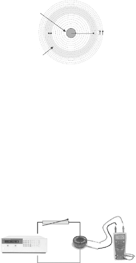
Current Carrying
Conductor of
1-4 A
r
b
= 0.5 cm
r
a
= 1.5 cm
Magnetic
Field Lines
Ferro-Magnetic
Material Coiled
with Copper Wires
FIGURE 6.3
To p view of ferrite core with current carrying conductor.
to the magnetic field
B,
the loop area
A,
the winding number of turns
N,
and
the frequency of the current
f
.
The experimental setup to measure the induced voltage
V
emf
[
=
NB
t
) where the negative sign is due to Lenz's law] from the toroid-based
magnetic energy harvester via the current-carrying power cable is shown in
Figure 6.4
. The current flowing in the circuit varies from 1 to 4 A by adjusting
the voltage knob of the AC power supply. Due to the high current along the
circuitry, the high-wattage resistor load bank is utilized. A summary of the
measured and calculated induced emf (electromotive force) voltage for dif-
ference current flowing in the primary side power line is presented in
Table
6.1
.
It can be observed from
Table 6.1
that as the current flowing in the main-
stream power line increased from 1 to 4 A, the magnetic field
B
obtainable
at 1.5 cm away from the centre of the conductor also increased from 0.02 to
0.08 T. For that reason, the induced voltage generated at the output of the
toroid magnetic energy harvester was increased. During the characterization
process, the
r
a
distance of 1.5 cm was set as the reference point based on the
practical considerations of the physical diameter of the power cables and the
space taken by 500 turns of copper winding.
As i n
(
Resistor Load Bank
To r oid
AC Power Supply
Digital Multimeter
FIGURE 6.4
Characterization of a magnetic energy harvester based on Faraday's law.


Search WWH ::

Custom Search