Environmental Engineering Reference
In-Depth Information
are verified with the measured P-V curves as seen in
Figure 5.17
for varying
solar irradiance conditions, performed by a characterization setup based on
a fluorescent light source.
Figure 5.17
shows that all of the power curves peak
near the solar panel output voltage of 3.6 V. Conversely, for the power curve
(P-R) plotted in
Figure 5.18
, it can be observed that the MPPs of the solar
panel vary between 27 and 68 k
.Assuch, by setting the output voltage of
the solar panel fixed at 3.6 V, maximum output power can be harvested from
the solar panel under different solar irradiance. Within the indoor lighting
conditions of 380 to 1010 lux, the maximum electrical power that the solar
panel can harvest ranges from 180 to 480
W, respectively.
5.3.3
Thermal Energy Harvesting Subsystem
In the TEH subsystem, a miniaturized thermoelectric generator (TEG) housed
in the thermal energy harvester is used for converting thermal energy into
electrical energy. The thermal energy, generated from the heat source at a cer-
tain high temperature of
T
H
,ischannelled through the enclosed TEG via a thin
film of thermally and electrically conductive silver grease between them to
the heat sink. The residual heat accumulated in the heat sink is then released
to the surrounding ambient air at a lower temperature
T
C
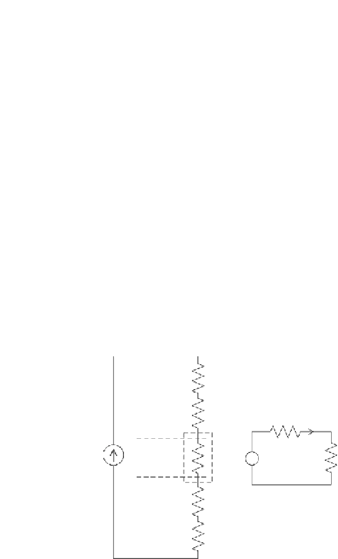
.Anequivalent ther-
mal circuit model of the thermal energy harvester that illustrates its thermal
and electrical characteristics is provided in
Figure 5.19
.
As observed in
Figure 5.19
, the temperature difference
T
TEG
across the
junctions of the TEG is lower than the temperature gradient,
T
C
,
that is externally imposed across the thermal energy harvester. This is because
T
=
T
H
−
T
H
R
con
(
H
)
R
g
(
H
)
R
s,TEG
i
TEG
Hot Side,
T
HJ
P
+
TEG
∆
=
P
*
R
TEG
T
TEG
V
oc
=
S
*∆
T
TEG
R
TEG
+
-
V
TEG
R
L
-
Cold Side,
T
CJ
R
g
(C)
R
con
(C)
T
c
FIGURE 5.19
Equivalent electrical circuit of the thermal energy harvester.


Search WWH ::

Custom Search