Environmental Engineering Reference
In-Depth Information
RF Transmitter
@ 433 MHz
Piezoelectric Push-Button
Igniter
Full-Wave
Rectifying Bridge
Storage
Capacitor
HT-12E
12-Bit Address/Data Encoder
MAX666
Linear Regulator
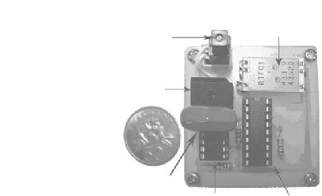
FIGURE 4.8
Photograph of the assembled prototype showing the key components.
Key components of the system are listed in
Figure 4.8
. They include the
piezoelectric push-button igniter, full-wave rectifying diode bridge, 2.2-
F
storage capacitor, MAX666 linear regulator, HT-12E 12-bit address/data
encoder, and a RF transmitter operating at 433 MHz. A Singapore 50-cent
coin has been included for relative size comparison. Comparing the sizes
between the piezoelectric push-button transmitter system and the coin as
illustrated in
Figure 4.8
, the requirement of miniature design for the system
has been achieved. In addition, the whole assembly is very light, weighing
about 12 g. Taking into account all the components used in the circuit design,
the total cost of assembly was less than SGD$35.00, which meets the low man-
ufacturing cost requirement. Hence, the small size, light weight, and low-cost
features of the piezoelectric push-button transmitter system make it suitable
for many wireless applications like a wireless remote controller.
4.1.3
Experimental Results
Several experimental tests were conducted to evaluate the performance of
the designed piezoelectric push-button igniter system. The open-circuit AC
voltage generated by the piezoelectric igniter as seen in
Figure 4.9
is fed into
a full-wave diode bridge rectifier, where the AC voltage is converted into DC
voltage, and then the DC voltage is stored in the capacitor. The DC voltage
waveform at the output of the diode bridge rectifier is shown in
Figure 4.10
.
Referring to
Figure 4.10
, it can be seen that the peak DC voltage is around
600 V. The zoomed view of the output DC voltage of the full-wave diode
bridge rectifier is shown in the bottom waveform of
Figure 4.10
.


Search WWH ::

Custom Search