Environmental Engineering Reference
In-Depth Information
in low-power operations where load currents are very low, on the order of
microamperes. Although a switch-mode voltage regulator is relatively more
complex, it has some superior advantages over a linear regulator, like high
power conversion efficiency, voltage step-up and step-down capability, and
more. After considering both the advantages and the disadvantages of ap-
plying the two types of voltage regulators for research, a linear regulator is
more suitable for this VEH research work.
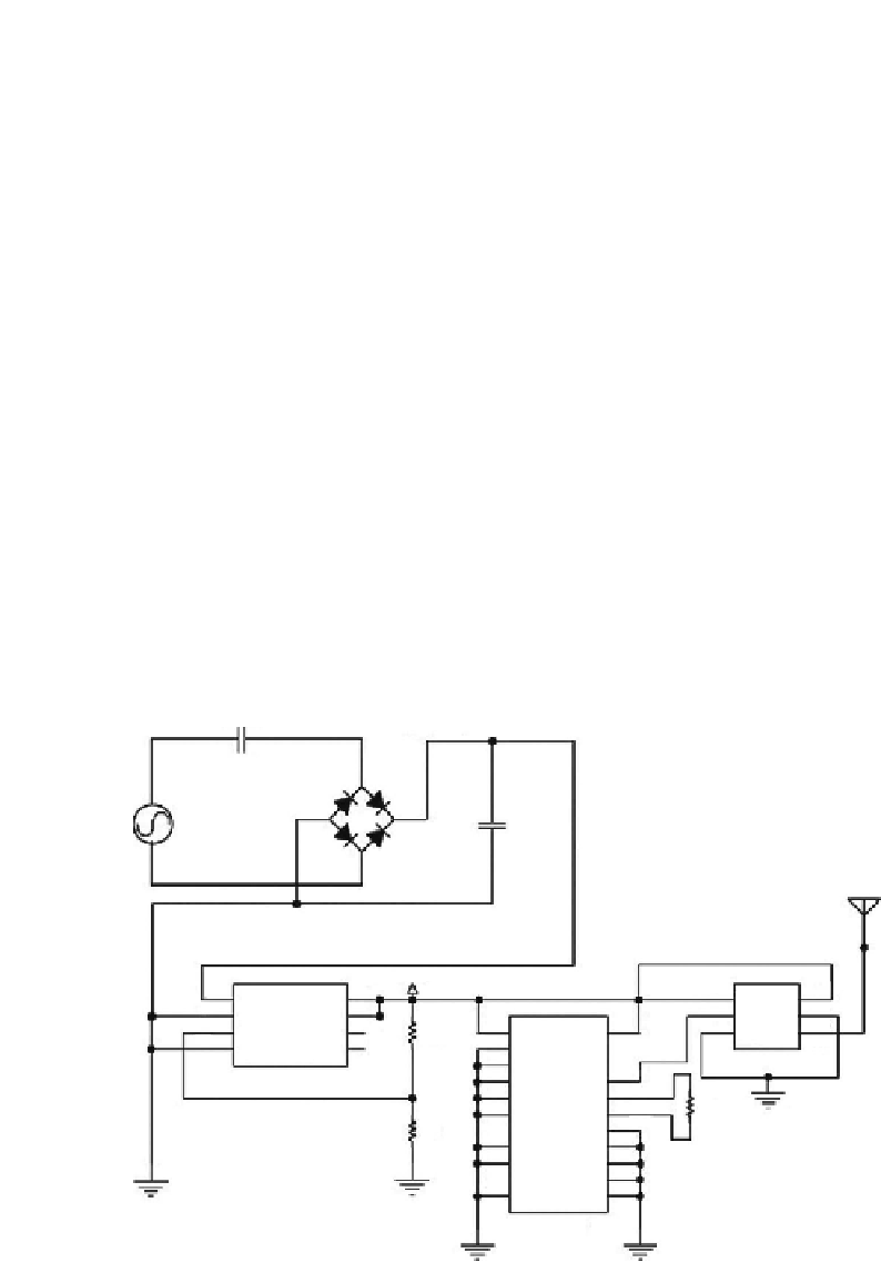
The schematic diagram of the proposed piezoelectric energy harvesting sys-
tem is shown in
Figure 4.7
. Referring to
Figure 4.7
, the principle of operation
of the piezoelectric energy harvester for powering a self-powered wireless
transmitter is illustrated. When the piezoelectric push button is depressed,
around 5 to 7 kV of AC voltage is generated. The generated AC voltage is
rectified into DC voltage by the full-wave rectifying diode bridge, and the
DC voltage is stored temporarily in the 2.2-
F capacitor. The presence of the
capacitor is not only to store harvested energy but also to help clamp down
the DC voltage to about 8 V and to smooth the DC voltage to constant voltage.
The unregulated DC voltage from the capacitor is regulated by the MAX666
linear regulator. The regulated output DC voltage of MAX666 is 3.3 V, which
is then used to operate the HT-12E encoder to transmit 12-bit address/data
information via the radio transmitter. The whole piezoelectric push-button
transmitter system is mounted on a printed circuit board (PCB) with a total
Cpiezo
Full-Wave Rectifying Bridge
18 pF
+
Storage
2.2 µF
Vp
Antenna
DC-DC Linear Regulator
+3.3 V
8
2
1
4
EN
IN
GND
VCC
GND
ANT
VIN+
VOUT
5
1
2
5
SD
SEN
1
3
6
3
18
6
A0
A1
A2
A3
A4
A5
VDD
VSET
LBI
1.5 M
2
4
7
GND
MAX666CPA
LBO
3
RTFQ1-433
4
17
16
15
DOUT
5
OSC1
6
7
750 K
OSC2
14
/TE
1M
13
A6
A7
AD11
8
9
12
AD10
11
AD9
10
GND
AD8
HT-12E
FIGURE 4.7
A circuit schematic of a piezoelectric energy harvesting circuit.


Search WWH ::

Custom Search