Environmental Engineering Reference
In-Depth Information
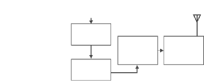
Energy from the Environment
Energy-
Conversion
Power
Processing
Unit
RF
Transmitter
Energy-
Storage
FIGURE 4.2
A block diagram of a self-powered wireless RF transmitter.
Referring to
Figure 4.2
, the key components of a self-powered wireless
transmitter system include a micropower impact-based piezoelectric gener-
ator, an energy storage device, a power processing unit (PPU), and a radio
transmitter. When a small mechanical force is depressed on the piezoelectric
push button, the kinetic energy is harvested by the piezoelectric igniter and
converted into electrical energy. The electrical energy is temporarily stored
in an energy storage device like a capacitor or battery and then regulated by
the PPU into regulated output voltage. After this, the regulated direct current
(DC) power provides energy for the radio-frequency (RF) transmitter circuit
to perform serial transmission via the radio transmitter to communicate with
the environmental sensors, control, and actuating systems deployed in the
smart environment.
4.1.1
Piezoelectric Push Button
Piezoelectric push buttons shown in
Figure 4.3
have been widely used in
industries for several purposes. One example is the integration of a push but-
ton in an igniter for gas lighting; it generates very high voltage at very low
mechanical impact force, and this high voltage is applied to an air gap to gen-
erate an electric arc. Referring to
Figure 4.3
, the piezoelectric igniter consists
of a cylindrical metal base that connects to the negative wire, and the other
positive wire is internally connected to the piezoelectric element. A depress-
ible ignition button-like structure is found on the top part of the igniter body.
When the piezoelectric push button is depressed, a spring inside will be com-
pressed. When the pressure exceeds a threshold, the spring-loaded hammer
will be released, which delivers a dynamic mechanical force to compress the
piezoelectric element as illustrated in
Figure 4.4
. Referring to
Figure 4.4
, the
external force mechanically strains the internal piezoelectric element; these
polarized unit cells shift and align in a regular pattern in the crystal lattice.
The discrete dipole effects accumulate, developing an electrostatic potential
between opposing faces of the element [110].
In the parallel mode of operation [79], the electrical field is generated (i.e.,
axis-3 in this case as shown in
Figure 4.4
)
across the same axis where the


Search WWH ::

Custom Search