Environmental Engineering Reference
In-Depth Information
supercapacitor is equivalent to the range of load resistances
R
L
between 10
to 56 k
.At
V
cap
(500 s), the 0.1-F supercapacitor is being charged to voltage
levels of 2.57 V with the MPPT scheme and 1.73 V without the MPPT scheme.
Comparing the two schemes, it is obvious that the charging performed by
the TEH system with MPPT is much higher than its counterpart without the
MPPT scheme. This is because the thermal energy harvester is maintained at
its near MPPs; hence, more electrical power is transferred to the supercapac-
itor. When the TEH system is operating with the MPPT scheme, the amount
of energy accumulated in the supercapacitor after 500 s is 0.28 J, which is two
times its counterpart of 0.15 J; hence, this exhibits the superior performance of
the TEH system with the MPPT scheme over its counterpart under a dynamic
loading condition.
3.3.3
Regulating a Buck Converter and Wireless Sensor Node
The TEH system is designed to power a commercially available wireless sen-
sor node supplied by Texas Instrument known as the wireless target board,
eZ430-RF2500T. A buck converter (LTC1877) obtained from Linear Technol-
ogy is inserted between the supercapacitor and the wireless sensor node to
provide a constant operating voltage of 2.8 V
DC
. The efficiency of the buck
converter is around 80% to 90%, consuming an operating current of 12
A.
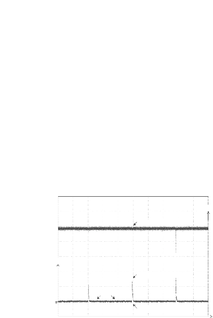
In this chapter, the operation of the wireless sensor node deployed in an ap-
plication field is illustrated in
Figure 3.12
.
Main : 125 k
2 s/div
V
V
/
Source Voltage (
V
in
)
5
4
3
I
/mA
20
2
Radio Transmission (
I
Tx
)
10
1
ADC Sensing
Load Current (
I
o
)
0
2
4
6
8
10
12
14
16
Time/sec
FIGURE 3.12
Operation of the wireless sensor node.


Search WWH ::

Custom Search