Information Technology Reference
In-Depth Information
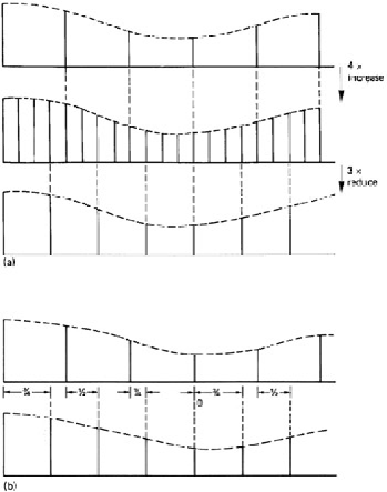
Figure 3.22:
At (a), fractional-ratio conversion of 3/4 in this example is by increasing to 4 input prior to reducing by
3. The inefficiency due to discarding previously computed values is clear. At (b), efficiency is raised since only
needed values will be computed. Note how the interpolation phase changes for each output. Fixed coefficients can
no longer be used.
As has been seen, a more efficient structure results from combining the processes. The result is exactly the same
structure as an integer-ratio interpolator, and requires an FIR filter. The impulse response of the filter is determined
by the lower of the two sampling rates, and, as before, it prevents aliasing when the rate is being reduced, and
prevents images when the rate is being increased. The interpolator has sufficient coefficient phases to interpolate
m
output samples for every input sample, but not all of these values are computed; only interpolations which
coincide with an output sample are performed. It will be seen in
Figure 3.22
(
b) that input samples shift across the
transversal filter at the input sampling rate, but interpolations are only performed at the output sample rate. This is
possible because a different filter phase will be used at each interpolation.
In the previous examples, the sample rate or spacing of the filter output had a constant relationship to the input,
which meant that the two rates had to be phase-locked. This is an undesirable constraint in some applications,
including warping processors. In a variable-ratio interpolator, values will exist for the points at which input samples
were made, but it is necessary to compute what the sample values would have been at absolutely any point in two
dimensions between available samples. The general concept of the interpolator is the same as for the fractional-
ratio convertor, except that an infinite number of filter phases is ideally necessary. Since a realizable filter will have
a finite number of phases, it is necessary to study the degradation this causes. The desired continuous temporal or
spatial axis of the interpolator is quantized by the phase spacing, and a sample value needed at a particular point
will be replaced by a value for the nearest available filter phase. The number of phases in the filter therefore
determines the accuracy of the interpolation.
The effects of calculating a value for the wrong point are identical to those of sampling with clock jitter, in that an
error occurs proportional to the slope of the signal. The result is program-modulated noise. The higher the noise
specification, the greater the desired time accuracy and the greater the number of phases required. The number of
phases is equal to the number of sets of coefficients available, and should not be confused with the number of
points in the filter, which is equal to the number of coefficients in a set (and the number of multiplications needed to
calculate one output value).
The sampling jitter accuracy necessary for eight-bit working is measured in picoseconds. This implies that
something like 32 filter phases will be required for adequate performance in an eight-bit sampling-rate convertor.