Information Technology Reference
In-Depth Information
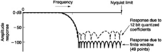
Figure 3.14:
Frequency response of a 49-point transversal filter with infinite precision (solid line) shows ripple due
to finite window size. Quantizing coefficients to 12 bits reduces attenuation in the stopband. (Responses courtesy
Philips Technical Review
)
The FIR structure is inherently phase linear because it is easy to make the impulse response absolutely
symmetrical. The individual samples in a digital system do not know in isolation what frequency they represent, and
they can only pass through the filter at a rate determined by the clock. Because of this inherent phase-linearity, a
FIR filter can be designed for a specific impulse response, and the frequency response will follow.
The frequency response of the filter can be changed at will by changing the coefficients. A programmable filter only
requires a series of PROMs to supply the coefficients; the address supplied to the PROMs will select the response.
The frequency response of a digital filter will also change if the clock rate is changed, so it is often less ambiguous
to specify a frequency of interest in a digital filter in terms of a fraction of the fundamental interval rather than in
absolute terms. The configuration shown in
Figure 3.9
serves to illustrate the principle. The units used on the
diagrams are sample periods and the response is proportional to these periods or spacings, and so it is not
necessary to use actual figures.
Where the impulse response is symmetrical, it is often possible to reduce the number of multiplications, because
the same product can be used twice, at equal distances before and after the centre of the window. This is known
as folding the filter. A folded filter is shown in
Figure 3.15
.
Figure 3.15:
A seven-point folded filter for a symmetrical impulse response. In this case K1 and K7 will be identical,
and the input sample can be multipled once, and the product fed into the output shift system in two different places.
The centre coefficient K4 appears once. In an even-numbered filter the centre coefficient would also be used twice.
[
2
]
van den Enden, A.W.M. and Verhoeckx, N.A.M., Digital signal processing: theoretical background.
Philips Tech.
Rev.
,
42
, 110-144, (1985)
[
3
]
McClellan, J.H., Parks, T.W. and Rabiner, L.R., A computer program for designing optimum FIR linear-phase
digital filters.
IEEE Trans. Audio and Electroacoustics
,
AU-21
, 506-526 (1973)
[
4
]
Dolph, C.L., A current distribution for broadside arrays which optimises the relationship between beam width and
side-lobe level.
Proc. IRE
,
34
, 335-348 (1946)
3.6 Interpolation
Interpolation is an important enabling technology on which a large number of practical digital video devices are
based. Some of the applications of interpolation are set out below:
1.
Digital video standards often differ from the sampling standard used inMPEG, particularly with respect to
the disposition of colour samples. Interpolation is needed to format video into the standard MPEG expects
and to return the signal to its original format after decoding. In low-bit rate applications such as Internet
video, the picture resolution may be reduced by downsampling. For display the number of pixels may have
to be increased again.
2.
In digital audio, different sampling rates exist today for different purposes. Rate conversion allows material
to be exchanged freely between such formats. Low-bit rate compressed channels may require a reduced
sampling rate as an input format.