Information Technology Reference
In-Depth Information
3.2 Transforms
Transforms are a useful subject because they can help to understand processes which cause undesirable filtering
or to design filters. The information itself may be subject to a transform. Transforming converts the information into
another analog. The information is still there, but expressed with respect to temporal or spatial frequency rather
than time or space. Instead of binary numbers representing the magnitude of samples, there are binary numbers
representing the magnitude of frequency coefficients. The close relationship of transforms to compression
technology makes any description somewhat circular as
Figure 3.4
shows. The solution adopted in this chapter is
to introduce a number of filtering-related topics, and to interpret these using transforms whenever a useful point
can be illustrated.
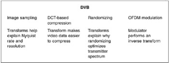
Figure 3.4:
Transforms are extensively found in convergent systems. They may be used to explain the operation of
a process, or a process may actually create a transform. Here the relationship between transforms and DVB is
shown.
Transforms are only a different representation of the same information. As a result what happens in the frequency
domain must always be consistent with what happens in the time or space domains. A filter may modify the
frequency response of a system, and/or the phase response, but every combination of frequency and phase
response has a corresponding impulse response in the time domain.
Figure 3.5
shows the relationship between the domains. On the left is the frequency domain. Here an input signal
having a given spectrum is input to a filter having a given frequency response. The output spectrum will be the
product of the two functions. If the functions are expressed logarithmically in deciBels, the product can be obtained
by simple addition.
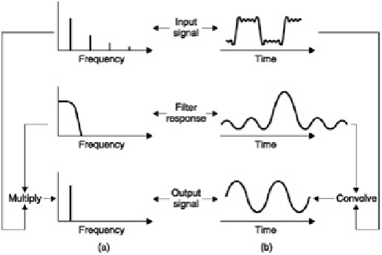
Figure 3.5:
If a signal having a given spectrum is passed into a filter, multiplying the two spectra will give the output
spectrum at (a). Equally transforming the filter frequency response will yield the impulse response of the filter. If this
is convolved with the time domain waveform, the result will be the output waveform, whose transform is the output
spectrum (b).
On the right, the time-domain output waveform represents the convolution of the impulse response with the input
waveform. However, if the frequency transform of the output waveform is taken, it must be the same as the result
obtained from the frequency response and the input spectrum. This is a useful result because it means that when
image or audio sampling is considered, it will be possible to explain the process in both domains. In fact if this is
not possible the phenomenon is incompletely understood.
3.3 Convolution
When a waveform is input to a system, the output waveform will be the convolution of the input waveform and the
impulse response of the system. Convolution can be followed by reference to a graphic example in
Figure 3.6
.
Where the impulse response is asymmetrical, the decaying tail occurs
after
the input. As a result it is necessary to
reverse the impulse response in time so that it is mirrored prior to sweeping it through the input waveform. The
output voltage is proportional to the shaded area shown where the two impulses overlap. If the impulse response is