Information Technology Reference
In-Depth Information
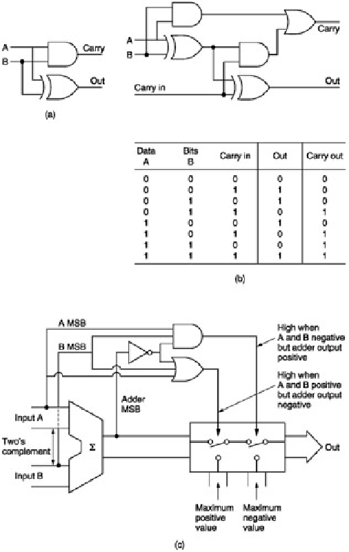
Figure 2.40:
(a) Half adder; (b) full-adder circuit and truth table; (c) comparison of sign bits prevents wraparound
on adder overflow by substituting clipping level.
Such a device is also convenient for inverting a two's complement number, in conjunction with a set of invertors.
The adder has one set of inputs taken to a false state, and the carry-in permanently held true, such that it adds one
to the one's complement number from the invertor.
When mixing by adding sample values, care has to be taken to ensure that if the sum of the two sample values
exceeds the number range the result will be clipping rather than overflow. In two's complement, the action
necessary depends on the polarities of the two signals. Clearly if one positive and one negative number are added,
the result cannot exceed the number range. If two positive numbers are added, the symptom of positive overflow is
that the most significant bit sets, causing an erroneous negative result, whereas a negative overflow results in the
most significant bit clearing. The overflow control circuit will be designed to detect these two conditions, and
override the adder output. If the MSB of both inputs is zero, the numbers are both positive, thus if the sum has the
MSB set, the output is replaced with the maximum positive code (0111 . . .). If the MSB of both inputs is set, the
numbers are both negative, and if the sum has no MSB set, the output is replaced with the maximum negative
code (1000 . . .). These conditions can also be connected to warning indicators.
Figure 2.40
(c) shows this system
in hardware. The resultant clipping on overload is sudden, and sometimes a PROM is included which translates
values around and beyond maximum to soft- clipped values below or equal to maximum.
A storage element can be combined with an adder to obtain a number of useful functional blocks which will crop up
frequently in digital signal processing.
Figure 2.41
(a) shows that a latch is connected in a feedback loop around an
adder. The latch contents are added to the input each time it is clocked. The configuration is known as an
accumulator in computation because it adds up or accumulates values fed into it. In filtering, it is known as a
discrete time integrator. If the input is held at some constant value, the output increases by that amount on each
clock. The output is thus a sampled ramp.
Figure 2.41
(b) shows that the addition of an invertor allows the difference between successive inputs to be
obtained. This is digital differentiation. The output is proportional to the slope of the input.
2.18 Gain control