Information Technology Reference
In-Depth Information
DVD is that it can be mastered in non-real time. This allows techniques such as aligning cuts with
I
-pictures to be
used. Also the quality obtained can be assessed and if artifacts are observed the process can be modified.
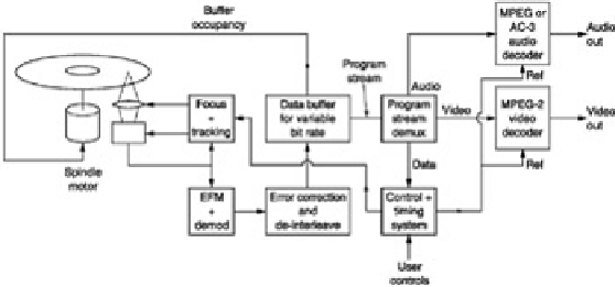
Figure 7.17
shows the block diagram of a typical DVD player, and illustrates the essential components. A CD-Video
player is similar. The most natural division within the block diagram is into the control/servo system and the data
path. The control system provides the interface between the user and the servo mechanisms, and performs the
logical interlocking required for safety and the correct sequence of operation.
Figure 7.17:
A DVD player's essential parts. See text for details.
The servo systems include any power-operated loading drawer and chucking mechanism, the spindle-drive servo,
and the focus and tracking servos already described.
Power loading is usually implemented on players where the disk is placed in a drawer. Once the drawer has been
pulled into the machine, the disk is lowered onto the drive spindle, and clamped at the centre, a process known as
chucking. In the simpler top-loading machines, the disk is placed on the spindle by hand, and the clamp is attached
to the lid so that it operates as the lid is closed. The lid or drawer mechanisms have a safety switch which prevents
the laser operating if the machine is open. This is to ensure that there can be no conceivable hazard to the user. In
actuality there is very little hazard in a DVD pickup. This is because the beam is focused a few millimetres away
from the objective lens, and beyond the focal point the beam diverges and the intensity falls rapidly. It is almost
impossible to position the eye at the focal point when the pickup is mounted in the player, but it would be foolhardy
to attempt to disprove this.
The data path consists of the data separator, the de-interleaving and error-correction process followed by a RAM
buffer which supplies the MPEG decoder.
The data separator converts the EFMplus readout waveform into data. Following data separation the error-
correction and de-interleave processes take place. Because of the interleave system, there are two opportunities
for correction, first, using the inner code prior to deinterleaving, and second, using the outer code after de-
interleaving. Interleaving is designed to spread the effects of burst errors among many different codewords, so that
the errors in each are reduced. However, the process can be impaired if a small random error, due perhaps to an
imperfection in manufacture, occurs close to a burst error caused by surface contamination. The function of the
inner redundancy is to correct single-symbol errors, so that the power of interleaving to handle bursts is
undiminished, and to generate error flags for the outer system when a gross error is encountered.
The EFMplus coding is a group code which means that a small defect which changes one channel pattern into
another could have corrupted up to eight data bits. In the worst case, if the small defect is on the boundary
between two channel patterns, two successive bytes could be corrupted. However, the final odd/even interleave on
encoding ensures that the two bytes damaged will be in different inner codewords; thus a random error can never
corrupt two bytes in one inner codeword, and random errors are therefore always correctable.
The de-interleave process is achieved by writing sequentially into a memory and reading out using a sequencer.
The outer decoder will then correct any burst errors in the data. As MPEG data are very sensitive to error the error-
correction performance has to be extremely good.
Following the de-interleave and outer error-correction process an MPEG program stream (see
Chapter 6
) emerges.
Some of the program stream data will be video, some will be audio and this will be routed to the appropriate
decoder. It is a fundamental concept of DVD that the bit rate of this program stream is not fixed, but can vary with
the difficulty of the program material in order to maintain consistent image quality. However, the disk uses constant
linear velocity rather than constant angular velocity. It is not possible to obtain a particular bit rate with a fixed
spindle speed.
The solution is to use a RAM buffer between the transport and the MPEG decoders. The RAM is addressed by
counters which are arranged to overflow, giving the memory a ring structure. Writing into the memory is done using
clocks derived from the disk whose frequency rises and falls with runout, whereas reading is done by the decoder
which, for each picture, will take as much data as is required from the buffer.