Information Technology Reference
In-Depth Information
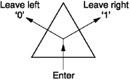
Figure 5.79:
Triangles are binary: entering by one side leaves a choice of two sides by which to leave.
Figure 5.79 shows that triangles are fundamentally binary. Digital transmission is serial, and compression works by
finding advantageous sequences in which to send information, for example the scanning of DCT coefficients. When
scanning triangles, if a scan enters via one edge, there are then only two sides by which to exit. This decision can
be represented by a single bit for each triangle, known as a
marching
bit.
Figure 5.80(a) shows a representative object, in this case a spheroid. Its surface has been roughly sampled to
create twelve vertices, and edges are drawn between the vertices to create triangles. The flat triangles create a
dodecahedron, and this may later be refined more closely to the spheroid with a forest split operation. For the
moment the goal is to transmit the vertices so that the triangles can be located. As adjacent triangles share
vertices, there are fewer vertices than triangles. In this example there are twenty triangles but only twelve vertices.
When a vertex is transmitted, the information may be required by more than one triangle. Transferring this
information to the next triangle in the scan sequence is obvious, but where the scan branches it is non-obvious and
a structure known as
vertex loop look-up table
is needed to connect vertex data. Only one vertex needs to have its
absolute coordinates transmitted. This is known as the
root vertex
. The remaining vertices can be coded by
prediction from earlier vertices so that only the residual needs to be sent.
In general it is impossible for a continuous scan sequence to visit all of the triangles. Figure 5.80(b) shows that if
cuts are made along certain edges, the triangles can be hinged at their edges. This is continued until they all lie in
the same plane to form a polygon (c). This process has created a binary tree along which the triangles can be
scanned, but it has also separated some of the vertices. Figure 5.80(c) apparently has 22 vertices, but ten of these
are redundant because they simply repeat the locations of the real vertices. Figure 5.80(d) shows how the vertex
loop look-up process can connect a single coded vertex to all its associated triangles.
In graphics terminology, the edges along which the polyhedron was cut form a rooted vertex tree. Each run of the
vertex tree terminates at a point where a cut ended. The extremities of the vertex tree correspond to the
concavities in the polygon. When the vertex loop is collapsed to zero area in the process of folding the polygon into
a solid body it becomes a vertex tree.