Information Technology Reference
In-Depth Information
In real television program material objects move around before a fixed camera or the camera itself moves. Motion
compensation is a process which effectively measures motion of objects from one picture to the next so that it can
allow for that motion when looking for redundancy between pictures.
Figure 1.9
shows that moving pictures can be
expressed in a three-dimensional space which results from the screen area moving along the time axis. In the case
of still objects, the only motion is along the time axis. However, when an object moves, it does so along the
optic
flow axis
which is not parallel to the time axis. The optic flow axis is the locus of a point on a moving object as it
takes on various screen positions.
Figure 1.9:
Objects travel in a three-dimensional space along the optic flow axis which is only parallel to the time
axis if there is no movement.
It will be clear that the data values representing a moving object change with respect to the time axis. However,
looking along the optic flow axis the appearance of an object only changes if it deforms, moves into shadow or
rotates. For simple translational motions the data representing an object are highly redundant with respect to the
optic flow axis. Thus if the optic flow axis can be located, coding gain can be obtained in the presence of motion.
A motion-compensated coder works as follows. A reference picture is sent, but is also locally stored so that it can
be compared with another picture to find motion vectors for various areas of the picture. The reference picture is
then shifted according to these vectors to cancel inter- picture motion. The resultant
predicted
picture is compared
with the actual picture to produce a
prediction error
also called a
residual
. The prediction error is transmitted with
the motion vectors. At the receiver the reference picture is also held in a memory. It is shifted according to the
transmitted motion vectors to re-create the predicted picture and then the prediction error is added to it to re-create
the original.
In prior compression schemes the predicted picture followed the reference picture. In MPEG this is not the case.
Information may be brought back from a later picture or forward from an earlier picture as appropriate.
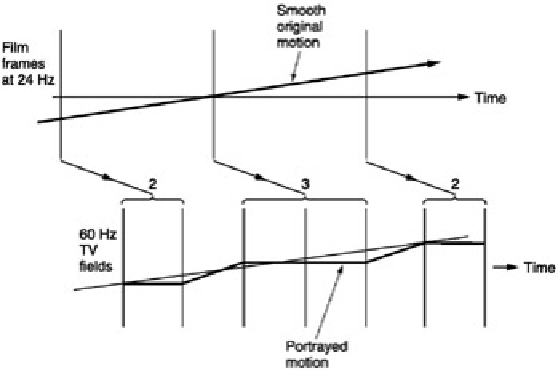
Figure 1.10:
Telecine machines must use 3:2 pulldown to produce 60 Hz field rate video.
1.7.4 Film-originated video compression
Film can be used as the source of video signals if a telecine machine is used. The most common frame rate for film
is 24 Hz, whereas the field rates of television are 50 Hz and 60 Hz. This incompatibility is patched over in two
different ways. In 50 Hz telecine, the film is simply played slightly too fast so that the frame rate becomes 25 Hz.
Then each frame is converted into two television fields giving the correct 50 Hz field rate. In 0 Hz telecine, the film
travels at the correct speed, but alternate frames are used to produce two fields then three fields. The technique is