Information Technology Reference
In-Depth Information
surplus synchronizing patterns. However, in a non-ideal system it might be advantageous to have frequent
resynchronizing. In DVB, for example, additional constraints are placd on the slice size.
5.15 Handling interlaced pictures
MPEG-1 does not support interlace, whereas MPEG-2 and MPEG-4 do. Spatial coding, predictive coding and
motion compensation can still be performed using interlaced source material at the cost of considerable complexity.
Despite that complexity, MPEG cannot be expected to perform as well with interlaced material.
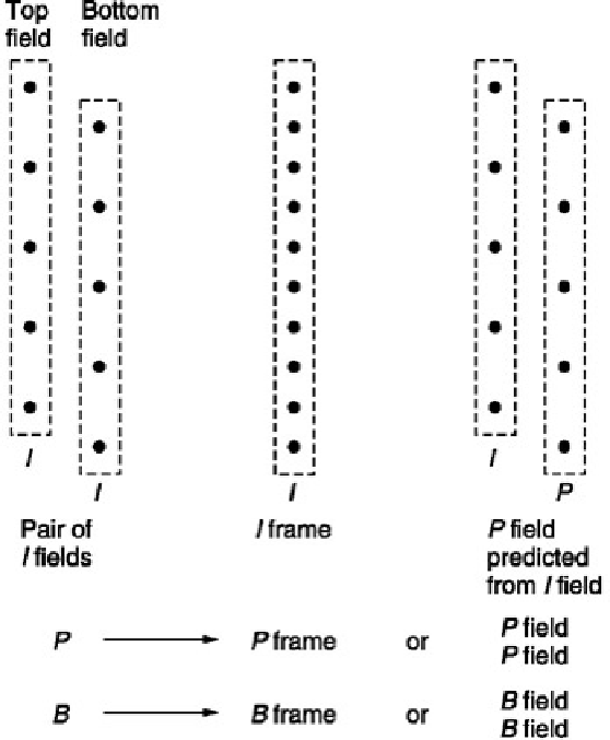
Figure 5.36 shows that in an incoming interlaced frame there are two fields each of which contain half of the lines in
the frame. In MPEG-2 and MPEG-4 these are known as the
top field
and the
bottom field
. In video from a camera,
these fields represent the state of the image at two different times. Where there is little image motion, this is
unimportant and the fields can be combined, obtaining more effective compression. However, in the presence of
motion the fields become increasingly decorrelated because of the displacement of moving objects from one field
to the next.
This characteristic determines that MPEG must be able to handle fields independently or together. This dual
approach permeates all aspects of MPEG and affects the definition of pictures, macroblocks, DCT blocks and zig-
zag scanning.
Figure 5.36 also shows how MPEG-2 designates interlaced fields. In picture types
I
,
P
and
B
, the two fields can be
superimposed to make a
frame-picture
or the two fields can be coded independently as two
field- pictures
. As a
third possibility, in
I
pictures only, the bottom field-picture can be predictively coded from the top field-picture to
make an
IP
frame- picture.
Figure 5.36:
An interlaced frame consists of top and bottom fields. MPEG-2 can code a frame in the ways shown
here.
A frame-picture is one in which the macroblocks contain lines from both field types over a picture area 16 scan
lines high. Each luminance macroblock contains the usual four DCT blocks but there are two ways in which these
can be assembled. Figure 5.37(a) shows how a frame is divided into
frame DCT
blocks. This is identical to the
progressive scan approach in that each DCT block contains eight contiguous picture lines. In 4:2:0, the colour
difference signals have been downsampled by a factor of two and shifted as was shown in Figure 2.17. Figure
5.37(a) also shows how one 4:2:0 DCT block contains the chroma data from 16 lines in two fields.