Information Technology Reference
In-Depth Information
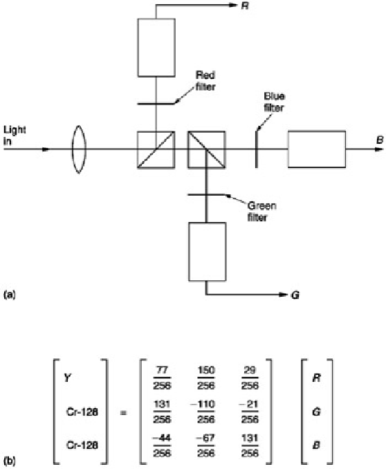
Figure 5.12:
(a) A simple colour system uses three primaries and transmits a complete picture for each. This is
incompatible with monochrome and uses too much bandwidth. Practical systems use colour difference and
luminance signals which are obtained by a weighted calculation as shown in (b).
A monochrome camera produces a single luminance signal
Y
whereas a colour camera produces three signals, or
components
,
R
,
G
and
B
which are essentially monochrome video signals representing an image in each primary
colour.
RGB
and
Y
signals are incompatible, yet when colour television was introduced it was a practical necessity
that it should be possible to display colour signals on a monochrome display and vice versa. Creating or
transcoding
a luminance signal from
R
,
G
and
B
is relatively easy. Figure 5.11 showed the spectral response of the
eye which has a peak in the green region. Green objects will produce a larger stimulus than red objects of the
same brightness, with blue objects producing the least stimulus. A luminance signal can be obtained by adding
R
,
G
and
B
together, not in equal amounts, but in a sum which is
weighted
by the relative response of the eye. Thus:
Y
= 0.3
R
+ 0.59
G
+ 0.11
B
If
Y
is derived in this way, a monochrome display will show nearly the same result as if a monochrome camera had
been used in the first place.
The results are not identical because of the non-linearities introduced by gamma correction.
As colour pictures require three signals, it should be possible to send
Y
and two other signals which a colour
display could arithmetically convert back to
R
,
G
and
B
. There are two important factors which restrict the form
which the other two signals may take. One is to achieve reverse compatibility. If the source is a monochrome
camera, it can only produce
Y
and the other two signals will be completely absent. A colour display should be able
to operate on the
Y
signal only and show a monochrome picture. The other is the requirement to conserve
bandwidth for economic reasons.
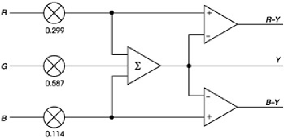
Figure 5.13:
Colour components are converted to colour difference signals by the transcoding shown here.