Information Technology Reference
In-Depth Information
coder will be reduced with a smaller compression factor. For moderate compression, a simple codec will be more
cost effective. On the other hand, as the compression factor is increased, it will be necessary to employ a more
complex coder to maintain quality.
MPEG Layer I is a simplified version of MUSICAM which is appropriate for the mild compression applications at low
cost. Layer II is identical to MUSICAM and is used for DAB and for the audio content of DVB digital television
broadcasts. Layer III is a combination of the best features of ASPEC and MUSICAM and is mainly applicable to
telecommunications where high compression factors are required.
At each layer, MPEG Audio coding allows input sampling rates of 32, 44.1 and 48 kHz and supports output bit rates
of 32, 48, 56, 64, 96, 112, 128, 192, 256 and 384 kbits/s. The transmission can be mono, dual channel (e.g.
bilingual), or stereo. Another possibility is the use of joint stereo mode in which the audio becomes mono above a
certain frequency. This allows a lower bit rate with the obvious penalty of reduced stereo fidelity.
The layers of MPEG Audio coding (I, II and III) should not be confused with the MPEG-1 and MPEG-2 television
coding standards. MPEG-1 and MPEG-2 flexibly define a range of systems for video and audio coding, whereas
the layers define types of audio coding.
The earlier MPEG-1 standard compresses audio and video into about 1.5 Mbits/s. The audio coding of MPEG-1
may be used on its own to encode one or two channels at bit rates up to 448 kbits/s. MPEG-2 allows the number of
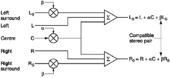
channels to increase to five: Left, Right, Centre, Left surround and Right surround. In order to retain reverse
compatibility with MPEG-1, the MPEG-2 coding converts the five-channel input to a compatible two-channel signal,
L
o
, R
o
, by matrixing
[
25
]
as shown in
Figure 4.28
. The data from these two channels are encoded in a standard
MPEG-1 audio frame, and this is followed in MPEG-2 by an ancillary data frame which an MPEG-1 decoder will
ignore. The ancillary frame contains data for another three audio channels.
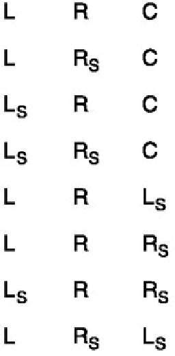
Figure 4.29
shows that there are eight
modes in which these three channels can be obtained. The encoder will select the mode which gives the least data
rate for the prevailing distribution of energy in the input channels. An MPEG-2 decoder will extract those three
channels in addition to the MPEG-1 frame and then recover all five original channels by an inverse matrix which is
steered by mode select bits in the bitstream.
Figure 4.28:
To allow compatibility with two-channel systems, a stereo signal pair is derived from the five surround
signals in this manner.
Figure 4.29:
In addition to sending the stereo compatible pair, one of the above combinations of signals can be
sent. In all cases a suitable inverse matrix can recover the original five channels.