Information Technology Reference
In-Depth Information
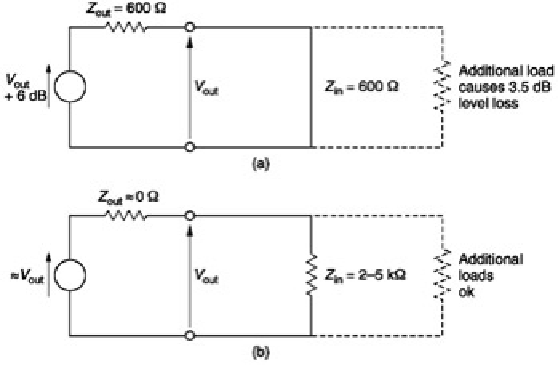
Figure 4.4:
(a) Traditional impedance matched source wastes half the signal voltage in the potential divider due to
the source impedance and the cable. (b) Modern practice is to use low-output impedance sources with high-
impedance loads.
In the absence of a fixed impedance it is now meaningless to consider power. Consequently only signal voltages
are measured. The reference remains at 0.775 V, but power and impedance are irrelevant. Voltages measured in
this way are expressed in dB(u); the commonest unit of level in modern systems. Most installations boost the
signals on interface cables by 4 dB. As the gain of receiving devices is reduced by 4 dB, the result is a useful noise
advantage without risking distortion due to the drivers having to produce high voltages. In order to make the
difference between dB(m) and dB(u) clear, consider the lossless matching transformer shown in
Figure 4.5
. The
turns ratio is 2:1 therefore the impedance matching ratio is 4:1. As there is no loss in the transformer, the power in
is the same as the power out so that the transformer shows a gain of 0 dB(m). However, the turns ratio of 2:1
provides a voltage gain of 6 dB(u). The doubled output voltage will develop the same power into the quadrupled
load impedance.
Figure 4.5:
A lossless transformer has no power gain so the level in dB(m) on input and output is the same.
However, there is a voltage gain when measurements are made in dB(u).
171
In a complex system signals may pass through a large number of processes, each of which may have a different
gain.
Figure 4.6
shows that if one stays in the linear domain and measures the input level in volts rms, the output
level will be obtained by multiplying by the gains of all the stages involved. This is a complex calculation.
Figure 4.6:
In complex systems each stage may have voltage gain measured in dB. By adding all of these gains
together and adding to the input level in dB(u), the output level in dB(u) can be obtained.
The difference between the signal level with and without the presence of a device in a chain is called the
insertion
loss
measured in dB. However, if the input is measured in dB(u), the output level of the first stage can be obtained
by adding the insertion loss in dB. The output level of the second stage can be obtained by further adding the loss