Information Technology Reference
In-Depth Information
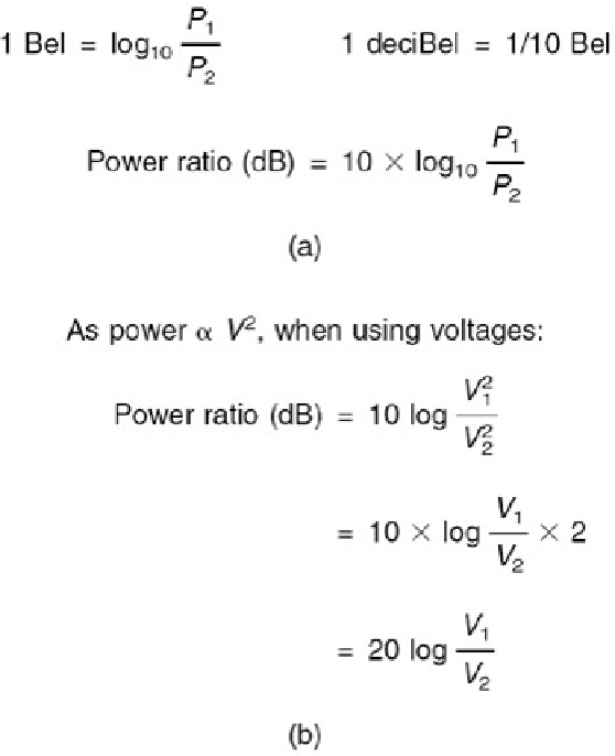
Figure 4.3:
(a) The Bel is the log of the ratio between two powers, that to be measured and the reference. The Bel
is too large so the deciBel is used in practice. (b) As the dB is defined as a power ratio, voltage ratios have to be
squared. This is conveniently done by doubling the logs so the ratio is now multiplied by 20.
The Bel was found to be an excessively large unit for many purposes and so it was divided into 10 deciBels,
abbreviated to dB with a small d and a large B and pronounced 'deebee'. Consequently the number of dB is ten
times the log of the power ratio. A device such as an amplifier can have a fixed power gain which is independent of
signal level and this can be measured in dB. However, when measuring the power of a signal, it must be
appreciated that the dB is a ratio and to quote the number of dBs without stating the reference is about as
senseless as describing the height of a mountain as 2000 without specifying whether this is feet or metres. To
show that the reference is one milliWatt into 600 , the units will be dB(m). In radio engineering, the dB(W) will be
found which is power relative to one Watt.
Although the dB(m) is defined as a power ratio, level measurements in audio are often done by measuring the
signal voltage using 0.775 V as a reference in a circuit whose impedance is not necessarily 600 .
Figure 4.3
(b)
shows that as the power is proportional to the square of the voltage, the power ratio will be obtained by squaring
the voltage ratio. As squaring in logs is performed by doubling, the squared term of the voltages can be replaced by
multiplying the log by a factor of two. To give a result in deciBels, the log of the voltage ratio now has to be
multiplied by 20.
Whilst 600 matched-impedance working is essential for the long distances encountered with telephones, it is quite
inappropriate for analog audio wiring in the studio or the home. The wavelength of audio in wires at 20 kHz is 15
km. Most studios are built on a smaller scale than this and clearly analog audio cables are
not
transmission lines
and their characteristic impedance is swamped by the devices connected at each end. Consequently the reader is
cautioned that anyone who attempts to sell exotic analog audio cables by stressing their transmission line
characteristics is more of a salesman than a physicist.
In professional analog audio systems impedance matching is not only unnecessary it is also undesirable.
Figure
4.4
(a) shows that when impedance matching is required the output impedance of a signal source must be
artificially raised so that a potential divider is formed with the load. The actual drive voltage must be twice that
needed on the cable as the potential divider effect wastes 6 dB of signal level and requires unnecessarily high
power supply rail voltages in equipment. A further problem is that cable capacitance can cause an undesirable HF
roll-off in conjunction with the high source impedance. In modern professional analog audio equipment, shown in
Figure 4.4
(b) the source has the lowest output impedance practicable. This means that any ambient interference is
attempting to drive what amounts to a short circuit and can only develop very small voltages. Furthermore, shunt
capacitance in the cable has very little effect. The destination has a somewhat higher impedance (generally a few
k) to avoid excessive currents flowing and to allow several loads to be placed across one driver.