Information Technology Reference
In-Depth Information
Figure 3.65:
In digital image stabilizing the optic flow axis of objects in the input video is measured as in (a). This
motion is smoothed to obtain a close approximation to the original motion (b). If this is subtracted from (a) the result
is the camera shake motion (c) which is used to drive the image stabilizer.
Operating over several pictures, the trend in camera movement can be separated from the shake by filtering, to
produce a position error for each picture. Each picture is then shifted in a DVE in order to cancel the position error.
The result is that the camera shake is gone and the camera movements appear smooth. In order to prevent the
edges of the frame moving visibly, the DVE also performs a slight magnification so that the edge motion is always
outside the output frame.
3.19 Motion-compensated de-interlacing
The most efficient way of de-interlacing is to use motion compensation.
Figure 3.66
shows that when an object
moves in an interlaced system, the interlace breaks down with respect to the optic flow axis. If the motion is known,
two or more fields can be shifted so that a moving object is in the same place in both. Pixels from both fields can
then be used to describe the object with better resolution than would be possible from one field alone. It will be
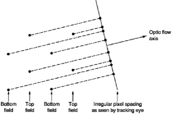
seen from
Figure 3.67
that the combination of two fields in this way will result in pixels having a highly irregular
spacing and a special type of filter is needed to convert this back to a progressive frame with regular pixel spacing.
At some critical vertical speeds there will be alignment between pixels in adjacent fields and no improvement is
possible, but at other speeds the process will always give better results.
Figure 3.66:
In the presence of vertical motion or motion having a vertical component, interlace breaks down and
the pixel spacing with respect to the tracking eye becomes irregular.