Hardware Reference
In-Depth Information
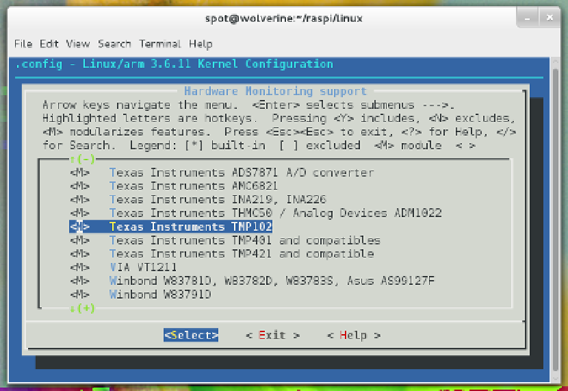
Figure 4-2.
Texas Instruments TMP102 sensor support enabled as a module
Sparkfun's breakout board makes connecting it to the Raspberry Pi simple. There are
six
pins
(or
leads
) coming off of the breakout. These pins are labeled on the back of
the breakout board, and the ones you care about are on the left side.
The first pin is Ground (GND), the second pin is the Serial Clock (SCL), the third pin
is the Serial Data Line (SDA), and the fourth pin is 5 V (V+). The SCL and SDA pins are
how the sensor sends/receives data across the I2C bus.
You should not need to use the pins labeled
ALT
or
ADD0
(they're on the right side of
the breakout board), unless you already have a conflicting device on the same I2C bus
and need to change the device number. Because this is the only device on the Rasp-
berry Pi GPIO I2C bus for this hack, you can just leave those pins alone. You can see
these labels on the TMP102 device, as shown in
Figure 4-3
.