Agriculture Reference
In-Depth Information
Undoubtedly only the very best of craftsmen could be tasked with setting out,
hewing and then building ornamental cut-moulded brick chimneys. Full-size
plans and elevations of the appropriate parts of the bases, shafts and heads
of the stacks would be drawn from which templets were obtained (Fig. 16).
Plans provided individual templets for the many types of brick shapes as well
as course templates, or moulds, to suit particular overall plan shapes, whereas
elevational drawings provided templets for the profiled shapes of most vertical
cut-mouldings. Shafts could be polygonal with canted bricks, some had contin-
uous patterning with simple geometrical shapes like a square or more ornate
with diamonds or hexagon detailing.
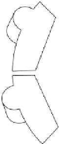
Where there was a vertical spiralling profile on the shaft, like the rope, or
cable, moulding, as seen in the Bridewell brick above, the establishment of
the templets was then altered to accommodate the change in profile through
the height, or gauge, of a particular brick (Figs 17 and 18). On elevation the
spiralling would be viewed as a regular stepping-off of measurements around
the circumference of the shaft. Obtaining those templets was achieved from
a plan view that established the offsets of both the lower and top beds of the
individual brick. Working to a centre line, these two templets - sometimes fit-
ted with corners to secure them to the brick as 'clip' moulds - would then be
held to the bed and to the top of the brick, at the correct vertical distance
apart, or gauge, and scribed. The brick could then be cut precisely by work-
ing between the two fixed points of reference and thus to the desired shape
(Fig. 19).
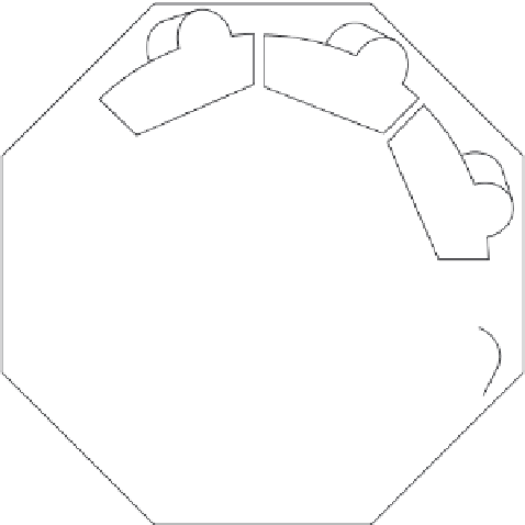
Figure 17
The positions of the
two templets A and B,
have been imposed by
the author onto the
plan to emphasise how
they were obtained.
(Drawing reproduced
by kind permission
of Robert Lamb, W
T Lambs, Bricks and
Arches Ltd)
A
B