Hardware Reference
In-Depth Information
Hardware configuration
It's now time to set up the hardware for this project. At this point, if you followed one of
the previous chapters, you should already have your Arduino Ethernet shield plugged into
the Arduino board, one Ethernet cable connecting the Ethernet shield, and your Internet
router. If that's not the case already, please do so.
The only thing you will have to connect in this project is the DHT11 sensor and the resist-
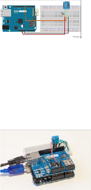
or. You can have an overview of the different connections you have to make by looking at
the following schematic diagram:
First, plug the DHT11 sensor to the breadboard. Then, connect pin numbers 1 and 2 of the
sensor using the 4.7k ohm resistor.
Now comes the power supply. Connect the pin number 1 of the sensor to the Arduino 5 V
and the pin number 4 to the Arduino GND. Finally, connect the pin number 2 of the DHT
sensor to the Arduino pin number 7.
At the end, it should look like the following image: