Graphics Reference
In-Depth Information
fixed-function processing is shown in Figure 3.3. In each sec-
tion, we will outline the shaders' operations and give a short
example of a vertex and a fragment shader that produce the
figure; we will then give a brief description of the GLSL shader
language, so you can see the language features that we use in
the examples. A more complete discussion of GLSL will come
in Chapter 5.
In the next chapter, we'll describe the
glman
tool that lets
you create and experiment with shaders without having to
write a complete application; here, it is useful if you see how
you could define this image with
glman
. Here is the GLIB file
that sets up the image and specifies the shaders to be used:
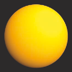
Figure 3.3.
A sphere with sim-
ple color, diffuse lighting, and
smooth shading.
Vertex Sphere.vert
Fragment Sphere.frag
Program Sphere
Color 1 0.5 0
Sphere 2.0 100 100
We will provide the vertex and fragment shader files for this example
later in this chapter.
Vertex Shaders
A GLSL vertex shader takes the vertex and environment information that is
stored by the OpenGL system and makes it available to you through a set
of uniform and atribute variables, so that you can do your own vertex com-
putations. Later in this chapter, we will outline some of the highlights of the
GLSL shader language, including these commonly used uniform and atribute
variables. Vertex shaders act on geometry that is usually given in model space
coordinates and produce geometry that is output in 3D clip space; all projec-
tion and clipping is done later in the graphics pipeline. Vertex shaders must
do much more than that, however. A GLSL vertex shader replaces these opera-
tions in the fixed-function geometry pipeline:
•
Vertex transformations.
•
Normal transformations.
•
Normal normalization (i.e., turn it into a unit vector).
•
Handling of per-vertex lighting.
•
Handling of texture coordinates.