Graphics Reference
In-Depth Information
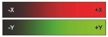
Figure 15.29.
Example color components for a 2D flow field.
The second texture is to encode the flow field. A 2D flow field has a (
vx
,
vy
)
velocity component pair at every point in the field. A good way to capture this
is with a 2D texture, leting the
y
component be represented by red and the
y
component by green. With floating point textures, the exact
(vx,vy)
can be
stored in each texel's
(r,g).
There is an unfortunate nuance here, though. Many graphics cards do not
yet accelerate bilinear sampling of floating point textures. However, nearest-
neighbor sampling of data such as a flow field often results in a very “chunky”
looking display. If you are using such a graphics card, then a beter solution is
to represent the flow velocities in an unsigned byte texture. For example, a 2D
circular flow field would be represented by a red scale that shows black for a
negative
x
component and red for positive, and black for a negative
y
component and green for positive, as shown in Figure 15.29.
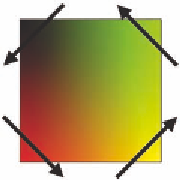
When these components are combined, the resulting 2D texture
field looks like Figure 15.30. For example, the lower-right corner is yel-
low because it has both a positive
x
and
y
velocity component. The
arrows in this figure show the direction that a circular LIC visualiza-
tion would take.
In practice, we don't actually care what the texture looks like, and
we rarely look at it except for fun. In fact, it is usually very difficult to
tell from the image just what the flow field really is. We don't care. We
just care about the data that is hiding in it.
Most of the work of LIC is in the fragment shader shown here:
Figure 15.30.
Using
color components to
encode flow velocities.
uniform int uLength;
uniform sampler2D uImageUnit;
uniform sampler2D uFlowUnit;
in vec2 vST;
out vec4 fFragColor;
void main( )
{