Graphics Reference
In-Depth Information
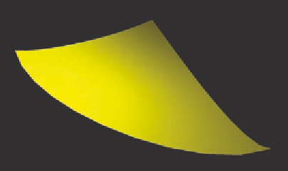
Figure 13.22.
A PN triangle (left) and the Bézier control points of the curved PN triangle (right).
The left-hand image in Figure 13.22 shows the original triangle with three
corner vertices and normals at those vertices. The general concept is to use this
information to turn each PN triangle into a triangular Bézier patch, and create
the Bézier control points. The Bézier patch equation can then be interpolated
to any level of tessellation. The right-hand image in Figure 13.22 shows the
Bézier control points of the curved PN triangle.
Now the geometry of a curved PN triangle that is defined by a triangu-
lar bicubic Bézier patch, which can be tessellated as shown in the images in
Figure 13.23.
Below we give a complete set of shaders that handle PN triangles. They
take input from a
.glib
file with uniform variables
uScale
, a scaling factor,
uShrink
, a shrinking factor for the geometry shader, and
uInner
and
uOuter
,
inner and outer tessellation levels respectively. A white light is assumed, and
its position is set in the geometry shader when the light intensity is computed.
All these could easily be replaced to use these shaders from an application.
Figure 13.23.
A tessellated PN triangle showing the individual tessellations (left) and shown as one smooth
surface (right).