Graphics Reference
In-Depth Information
gl_Position = uModelViewProjectionMatrix *
vec4( CG + uShrink * ( V[v] - CG ), 1. );
EmitVertex( );
}
void
main( )
{
V[0] = gl_PositionIn[0].xyz;
V[1] = gl_PositionIn[1].xyz;
V[2] = gl_PositionIn[2].xyz;
CG = ( V[0] + V[1] + V[2] ) / 3.;
ProduceVertex( 0 );
ProduceVertex( 1 );
ProduceVertex( 2 );
}
Sphere Subdivision
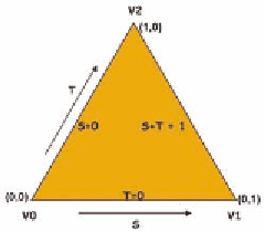
In this sphere subdivision example, we will start with a single
triangle in the first octant of the sphere whose vertices lie on the
positive coordinate axes. This triangle will be viewed as param-
eterized by two variables, which are multiplied by two adjacent
edges of the triangle to determine all the interior points of the
triangle. The triangle with this parameterization is shown in
Figure 12.6, where the coordinates shown represent the values
of the parameter pair.
This triangle is subdivided by choosing values of
s
and
t
for appropriate points and using them to define new triangles.
A parametric form of this is given by
Figure 12.6.
A triangle
parameterized by two edges.
Vst VsVVt VV
(,)
=+∗−+∗ −
0
(
)
(
),
1
0
2
0
with
s
,
t
≥ 0
and
s
+
t
≤ 1.
For example, in the triangles shown in Figure 12.7, the transition from
level 0 to level 1 is obtained by taking the three parameter pairs (0.5, 0), (0, 0.5),
and (0.5, 0.5) to define the three added points needed for the subdivision.
The vertex shader is straightforward and simply passes the
aVertex
value through to
gl_Position
. The fragment shader takes the input color and
calculates
fFragColor
by multiplying the light intensity by the color, as we
saw in earlier chapters. Neither of these needs to be presented further.