Graphics Reference
In-Depth Information
These inputs and outputs for the vertex shader are summed up in
Figure 7.2.
Geometry
If you are planning to use computed colors or textures for your final image,
based on the vertex coordinates of your graphical objects, it can be impor-
tant for your vertex shader to enable these coordinates to be passed to your
fragment shader so they can be used there. There are two kinds of geometry
that you can use for this:
model-space geometry
or
eye-space geometry
. We use a
prefix convention to show these; the MC prefix corresponds to model-space
geometry while the prefix EC corresponds to eye-space geometry. These are,
of course, two of the main 3D spaces you work with in computer graphics. We
can compute these primary kinds of geometry as follows.
•
For model-space geometry, you simply use the space in which your
model was defined:
vec3 MCposition = aVertex.xyz;
•
For eye space coordinates, you want to work with the geometry after all
modeling has been applied. This is straightforward using the ModelView
matrix:
vec3 ECposition = (uModelViewMatrix*aVertex).xyz;
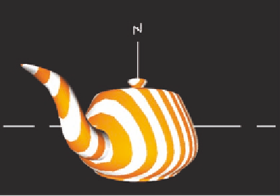
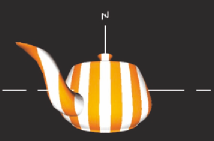
In Figure 7.3, we see how a shader can use the model coordinate (left) or
eye coordinate (right) values to generate colors. The fragment shaders for both
images create stripes that are parallel to the
YZ
plane, but the vertex shaders
differ in sending either model coordinates or eye coordinates to the fragment
shader to be used to determine the colors. The geometry in both cases has been
Figure 7.3.
The teapot with model coordinates determining the colors (left) and with eye coordinates deter-
mining the colors (right).