Graphics Programs Reference
In-Depth Information
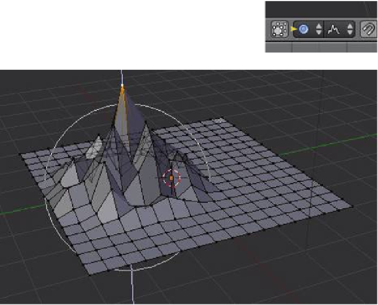
Figure 3.26
Ground terrain can be created by subdividing a
plane, then selecting a single vertex and moving
it up the z-axis with the proportional editing tool
on with random fall off.
Single vertex selected
Subdivided plane
Scroll the mouse wheel
to vary the size of the
influence circle.
3.21 Edge Loop Selection
When working with vertices, it is sometimes useful to be able to select edge loops. To dem-
onstrate this procedure you will have to create an object like the one shown in Figure 3.27.
Add a circle mesh object to the 3D window and tab to edit mode—the mouse cursor
should change to a white cross. Press the E key to extrude but do not move the mouse
cursor. Click the LMB on the mouse. You have created a
duplicate set of vertices. Now press the S key to scale the
duplicated vertices and move the mouse cursor towards
the center of the circle. Th is produces an inner circle.
Press the A key twice to deselect the inner circle then se-
lect all the vertices. With both circles selected, press the E
key (extrude) and move the mouse cursor away from the
mesh. By default, the extrusion takes place normally (at
right angles to the plane of the selected vertices, which
in this case is along the
z
-axis). You should have a mesh
object similar to the one shown in Figure 3.28 (left ).
To select a circular edge loop from this object, perform
the following steps in edit mode: click on the outer ring
with Alt + the RMB to select it; press Shift + Alt + the RMB
Learning
Unit 4
Loop Cut and
Slide
Figure 3.27
Click on the outer ring with
Alt + the RMB to select it.