Graphics Programs Reference
In-Depth Information
Edit mode in front view
Object mode in front view
Figure 15.8
Vertices scaled in
Vertices scaled in
Place the 3D
cursor here.
Tab into edit mode and extrude the circle on the
z
-axis to produce a cylinder. With the top
ring of vertices selected, extrude the shape again. With the third ring selected, press the S key
and move the cursor in towards the center of the cylinder. Continue on extruding and scaling
until you get a shape like the one in Figure 15.8 (left). The
finger will only have two parts, with a joint in the middle.
The vertices close together in the middle of the mesh are
where the joint will be; they act like a concertina hose on a
vacuum cleaner, allowing the mesh to bend. With the mesh
selected, tab into object mode and place the 3D cursor as
shown in Figure 15.8 (right).
Figure 15.9
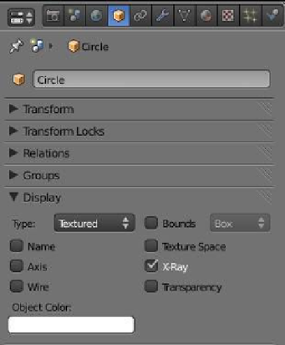
Note:
For the purpose of the demonstration, leave
the default circle object with the default radius of
1.000 Blender grid units. If the circle is scaled, the
finger mesh vertices may fall outside the armature's
field of influence, producing some unexpected re-
sults.
Deselect the mesh finger with the A key and add a sin-
gle bone armature as previously described. Since the cur-
sor was placed at the base of the finger on the centerline,


