Graphics Programs Reference
In-Depth Information
Figure 14.41
Figure 14.42
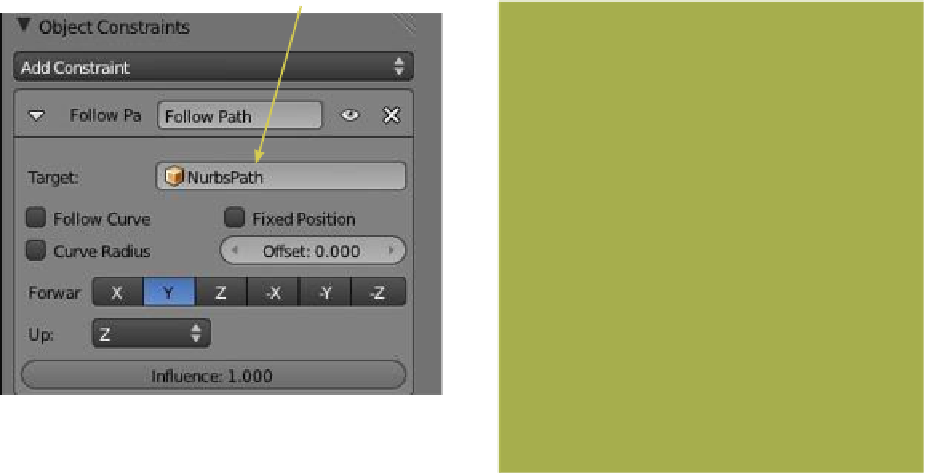
Set “NurbsPath” as the
target object.
of the screen. Therefore, select the curve path in the
3D window then go to the properties window - “Ob-
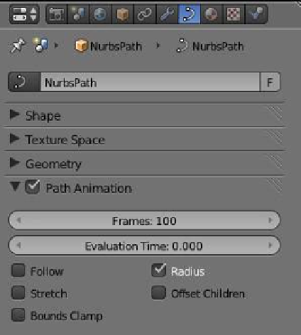
ject Data” button - “Path Animation” tab. Make sure
“Path Animation” is checked in the tab and note the values “Frames: 100” and “Evaluation
Time: 0.000” (Figure 14.42). Consider the “Frames: 100” value to mean that the curve path
length in the 3D window is divided into 100 intervals. Consider the “Evaluation Time”
value to mean the interval at which the linked object is residing along the curve path at a
given time. The default range is 0.00 to 100.00. If the number of intervals (frames) is in-
creased, adjust the evaluation time range accordingly. With the cube at the start of the path,
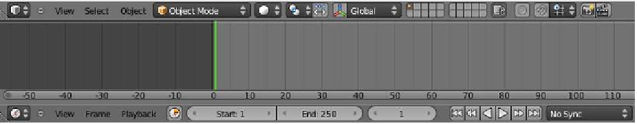
the “Evaluation Time” value is 0.000. By default, the timeline window shows a 250-frame
animation timeline with values “Start: 1” and “End: 250” and the vertical green cursor at
frame 1 (Figure 14.43).
Figure 14.43
Timeline window
Green cursor at frame 1
The curve path and the animation timeline are two separate identities. The object's
movement along the path may coincide with the timeline, but not necessarily. To demon-
strate this we will set the object to move along the path midway in the animation. In the
timeline window, move the cursor to frame 25. In the properties window - “Object Con-
straints” button - “Path Animation” tab, click the RMB on the “Evaluation Time” bar and