Graphics Programs Reference
In-Depth Information
•
Red Plane
- Name: Particle System
- Settings: Particle Settings
•
Green Plane
- Name: Particle System
- Settings: Particle Settings.001
•
Blue Plane
-
Figure 13.95
Name: Particle System
-
Settings: Particle Settings.002
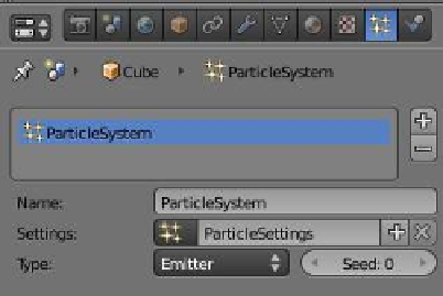
We previously stated that we have three separate par-
ticle systems; however, now we see that the three names
are all “Particle System,” but each one has a different set-
tings name. It's probably a good idea to do some renaming.
Change the names to the following:
Click to reveal the
drop down menu.
Figure 13.96
•
Red Plane
- Name: RedPSystem
- Settings: RedPSettings
•
Green Plane
- Name: GreenPSystem
- Settings: GreenPSettings
•
Blue Plane
-
“Particle Settings”
names
Name: BluePSystem
-
Settings: BluePSettings
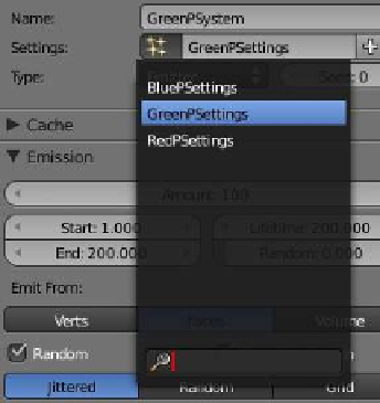
We should be able to see where we are now. To continue, in
the 3D window select the green plane—we are going to reassign
some settings. In the properties window - “Particles” button -
“Assignment” tab, click on the button just in front of the name
panel and next to “Settings.” The drop down menu that displays
has the names of the three particle settings data blocks (Figure 13.96). Whenever a new
group of particle settings is created, Blender puts it into a cache for reuse. You can see
these data blocks in the outliner window in data block
mode. The green plane is selected, so in the data block
drop down menu click on “BluePSettings.” We now have
the BluePSettings assigned to the GreenPSystem. If you
replay the particle generation animation, the green and
blue planes generate the same number of particles (Fig-
ure 13.97). Note that in the settings panel, a number 2
has appeared; this tells us that “BluePSettings” is being
used by two systems. The color of the particles is con-
trolled by the color of the plane object and the number
of particles emitted is set by the particle system settings.
Figure 13.97