Graphics Programs Reference
In-Depth Information
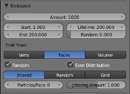
Figure 13.93
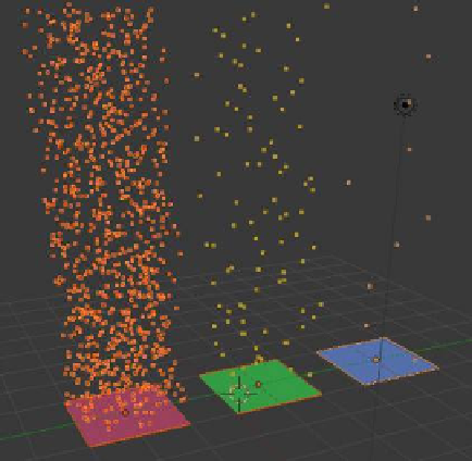
Figure 13.94
“Particles” button
Click to add a
particle system.
The number of particles emitted
from each plane object shows the
different systems.
Change the lifetime
value from 50 to 200.
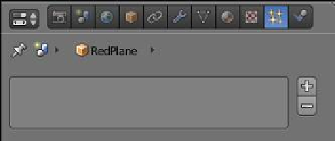
In the 3D window, select the red plane and go to the properties window - “Object” but-
ton. At the top of the window you will see “Plane” in the unique data block ID name panel
(Figure 13.92). Click on the name to highlight it, hit delete, type in “RedPlane,” and press
Enter. Select the green plane in the 3D window and rename it “GreenPlane,” and then simi-
larly for the blue plane.
We will now add particle systems to the planes. Select the red plane and click on the
“Particles” button in the properties window. Click on the + sign to add a particle system.
The particle system panel displays with all the tabs and buttons for controlling the settings
and has been set up with default values. Leave all the values as is except for the “Lifetime”
value in the “Emission” tab—change this value from the default 50 frames to 200 frames
(Figure 13.93). This will give us a better view of particles being generated. Do the same
for the other two planes and in addition change the “Amount” value in the “Emission” tab
to 100 for the green plane and 10 for the blue plane. Shift select all three planes in the 3D
window and hit Alt + the A key to play the animation of particles being generated. Cycle
through the animation in the timeline window to frame 180 and observe the particles (Fig-
ure 13.94). We have three different planes with three different particle systems—red plane:
1000 particles, green plane: 100 particles, blue plane: 10 particles.
Now in the 3D window select each plane separately and note in the properties window -
“Particles” button - “Assignment” tab the names that display in the “Name” and “Settings”
panels (Figure 13.95).