Graphics Programs Reference
In-Depth Information
Figure 13.14
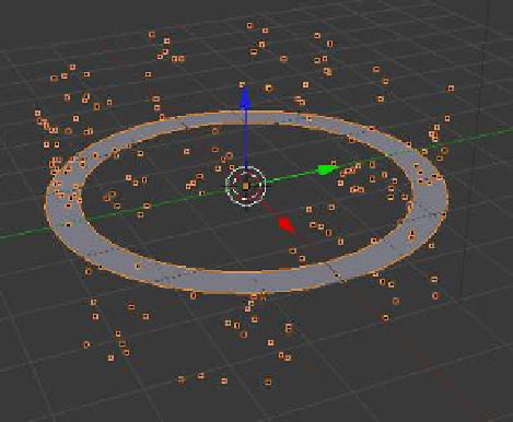
Figure 13.15
The outer vertices are extruded and
scaled down to form the inner ring.
Add a circle object to the scene and scale it up three times (press the S key + 3). Tab into edit
mode and with all vertices selected, press the E key (extrude), click the LMB followed by the
S key (scale), and move the mouse towards the center of the circle. When you are finished
creating the new shape, press the RMB (Figure 13.15). With the E key you have extruded
(created a new set of vertices) and the S key has allowed you to scale the set of new vertices.
Tab back to object mode and add a particle system. Go to the “Scene” tab, untick “Gravity,”
and play the animation. You will see particles being generated, but some are moving up and
some are moving down (Figure 13.16). Note that the default “Emission” tab - “Emit From”
value is “Faces” and the “Velocity” tab - “Emitter Geometry” - “Normal” value is 1.000.
We are therefore emitting particles from the faces of the object at 1 unit per second normal
to the circle's face. In modeling the circular plane object, some faces have been assigned
a negative normal value and some have been assigned a positive normal value, hence the
movement of the particles as seen in the anima-
tion. The normal values need to be recalculated to
align them in the same direction.
To realign the normals, tab into edit mode and
select all the vertices. With the cursor in the 3D
window, press Ctrl + the N key. “Make Normals
Consistent” will display in the side panel at the
lower LH corner of the screen. Tab back to object
mode and replay the animation. All the particles
will move in the same direction but not neces-
sarily upwards. Note that if the normal value is
changed to -1.000, the particles will move in the
opposite direction; set the normal value to -1.000
so the particles will move up.
Now let's have a close look at what is happen-
ing to the particles. If you look at the values in the
Figure 13.16