Hardware Reference
In-Depth Information
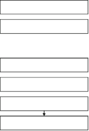
Create a reference program for CPU
Determine program parts
suitable for FE-GA processing
Create FDLs
Divide a process into threads
Check FDLs with FDL checker
and debug on FE-GA simulator
Create a data flow graph (DFG)
Convert FDLs into objects
with FDL assembler
Map DFG with FE-GA editor
Compress and combine objects
with FDL linker
Create FE-GA controlling codes
Debug on FE-GA and CPU
integrated simulator or on a real chip
Fig. 3.56
Software development steps for system with FE-GA
The constraint checker verifies both types of FDL files in terms of grammars and
specifications and generates verified FDL files. Then the assembler converts the
FDL files into a sequence object and a thread object, respectively. Finally, the FDL
linker combines both object files into a linked object with section information that
includes the address of its placement in a memory. It also compresses the object by
combining common instructions among the operation cells so that the object is
placed in the configuration buffer of the FE-GA.
The software development process in a system with an FE-GA is shown in
Fig.
3.56
. The process is rather complicated so as to obtain the optimal perfor-
mance. Users first create a reference program implementing a target application,
which is executable on a CPU. Then, FE-GA executable parts in the program are
determined by considering whether such parts can be mapped on the operation
array of the FE-GA in both a parallel and pipelined manner. Because operation
resources, such as the operation cells and the local memory, are limited, users need
to divide an FE-GA executable part into multiple threads. Then data flows are
extracted in each thread to create a data flow graph (DFG). Data placement on
multiple banks of the local memory is also studied in such a way that the data are
provided to the operation cells continuously in parallel. Users then program the
operation cells' functions and intercell wirings, taking into consideration the timing
of data arrival on each cell, according to the DFG and the data placement, using the
FE-GA editor. The program is debugged using the FE-GA simulator in the next step.


Search WWH ::

Custom Search