Hardware Reference
In-Depth Information
In tern al bu s
Sequence manager (SEQM)
In terru ption /
DMA request
LS Cells Local memory
Cell control bus
Operation cells
(24
LS
CRAM
8 cells)
MLT
MLT
MLT
MLT
MLT
MLT
MLT
MLT
+
ALU
ALU
ALU
ALU
ALU
ALU
ALU
ALU
ALU
ALU
ALU
ALU
ALU
ALU
ALU
ALU
ALU
ALU
ALU
ALU
ALU
ALU
ALU
ALU
LS
LS
LS
LS
LS
LS
LS
LS
LS
CRAM
CRAM
CRAM
CRAM
CRAM
CRAM
CRAM
CRAM
CRAM
System
bus
Sys.
bus
I/F
External
I/O
Crossbar network (XB)
(10 cells)
(10 banks)
Configuration manager (CFGM)
Compiled RAM
(4-16-KB, 2-Port)
ALU
ALU cells
MLT
Mult. cells
LS
Load/store cells
CRAM
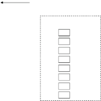
Fig. 3.47
Block diagram of fl exible engine/generic ALU array (FE-GA)
background transfer mechanism for efficient configuration control and a sequence
manager for autonomous sequence control, which enables it to operate as a highly
independent subsystem. With the FE-GA, various general-purpose accelerators
can be realized for media processing in connection with favorable control CPUs
(sub-CPUs).
3.2.1
Architecture Overview
Figure
3.47
illustrates the architecture of the FE-GA, which consists of an operation
block and a control block. The operation block is composed of two-dimensionally
arrayed arithmetic logic unit (ALU)/multiplication (MLT) cells whose functions
and connections to neighboring cells are dynamically changeable, a multiple-banked
local memory (LM) for data storage, load/store (LS) cells which generate addresses
for the LM, and a crossbar (XB) network supporting internal data transfer between
the LS cells and the LM. The LM is divided into plural banks (CRAMs). The control
block consists of a configuration manager (CFGM) that manages the configuration
data for the operation block and a sequence manager (SEQM) that controls the
state of the operation block. The FE-GA is highly optimized in terms of power and
performance in media processing for embedded systems.


Search WWH ::

Custom Search