Hardware Reference
In-Depth Information
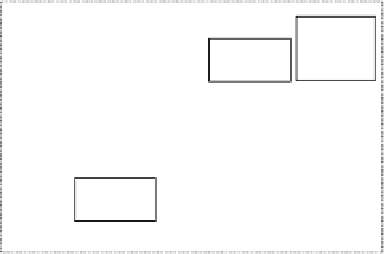
Fig. 6.32
RP-X application
system diagram
USB
Mouse
USB
Camera
USB Hub
USB Host
Controller
Hard Disk Drive
OS
lib
Appli.
Off-chip Interconnect
RP-X
Off-chip
Bus
Controller
CPU
#0
CPU
#1
CPU
#2
CPU
#3
SATA
Controller
On-chip Interconnect
DRAM
Controller
LDC
Controller
Video
encoder
Frame
buffer
Plane 0
Display
DRAM
effects. However, the application presented here has been modified to perform the
three visual effects in parallel to take advantage of a multicore processor.
The original SUSAN program accepts an image file stored in the portable gray
map (PGM) format as an input, reads the size of image and subsequent 8-bit gray-
scale images, and distributes the input to one of the visual effect algorithms. In this
implementation, however, the visual images are captured via the USB video class
(UVC) device and stored in the YUY2 format once and then converted into the 8-bit
grayscale format as the input to each visual effect algorithm. The size of the image
is smaller than 320 × 240 pixels and is one of the sizes supported by the USB cam-
era. Figure
6.32
shows the system diagram of the RP-X application.
The software architecture of the RP-X application is shown in Fig.
6.33
. The
SUSAN process creates four threads: “input,” “smoothing,” “edges,” and “corners.”
The “input” thread converts the captured image in the YUY2 format into the 8-bit
grayscale format. The “smoothing” thread smoothes shapes. The “edges” thread
finds edges in the image. The “corners” thread finds corners in the image. The system
is built to take advantage of the X-window system on the Linux operating system.


Search WWH ::

Custom Search