Hardware Reference
In-Depth Information
LCPG
INTC
CPU #0
CPU #1
CPU #2
CPU #3
DMAC
PCIe
SHPB
Internal system bus
WDT
TMU
HAC
Ether
USB
DU
HPB
LBSC
DBSC
Peripheral bus
CPG
GPIO
HSPI
SCIF
I2C
SSI
SDIF
ROM
RAM
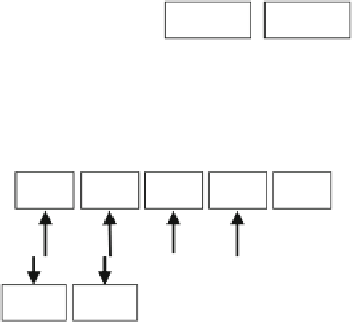
Fig. 5.10
Block diagram of the multicore processor
controller (LBSC) supporting connection to burst ROM, a DMAC, a sophisticated
interrupt controller (INTC), and several on-chip peripherals including the display
unit (DU), Ethernet controller, general-purpose I/O (GPIO), and serial communica-
tion interfaces (SCIF).
These hardware modules are connected through an internal system bus and a
peripheral bus. SHPB and HPB are bus bridges that connect the internal system bus
with the peripheral bus. The CPU cores, display unit, Ether, and USB are initiator
modules that can request access to other modules connected to the internal system
bus. HPB, SHPB, LBSC, and DBSC are target modules that initiators can access
through the internal system bus. DMAC and PCI Express (PCIe) are initiator mod-
ules as well as target modules on the internal system bus. These hardware modules
are mapped onto the processor's physical address space, which the initiators use to
gain access to processor resources.
In a multidomain system architecture, system designers assign domains to the
different CPU cores and processor resources, such as memory and peripherals.
They might also allocate shared memory resources that the domains can use to
communicate with each other. The operating system in each domain controls the
CPU cores and the other initiator modules so that they use the assigned processor
resources. Thus, the applications running on the operating system cannot use the
processor resources assigned to another domain. However, as we mentioned pre-
viously, the system could break down due to unintentional software malfunctions
in the operating system because the CPU core can access any processor resources.
An access-control mechanism in the multicore processor can help prevent such
access.


Search WWH ::

Custom Search