Hardware Reference
In-Depth Information
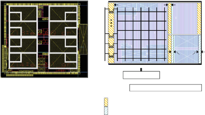
120
µ
m
70
µ
m
C0
C1
U0
U1
C2
C3
Core
U2
U3
URAM
U6
U7
C6
C7
50
µ
m
U4
U5
C4
C5
VSS
VSWC for Core
VSWC for URAM
VSSM
(virtual ground)
Power Control Register
VSWC
: Power Switch Controller
LCPG: Local Clock Pulse Generator
: Power Switch for Core
: Power Switch for URAM
Fig. 4.14
Power domain structure of 8 CPU cores with 8 URAMs
Table 4.4
Power modes of CPU cores
CPU power modes
Normal
Light sleep
Sleep
Resume
Power-off
Clock for CPU and URAM
On
Off
Off
Off
Off
Clock for I/D-cache
On
On
Off
Off
Off
Power supply for CPU
On
On
On
Off
Off
Power supply for URAM
On
On
On
On
Off
Leakage current
a
(mA)
162
162
162
22
0
a
Measured at room temperature at 1.0 V, eight-core total
4.3.3
Synchronization Support Hardware
The RP-2 has barrier registers to support CPU core synchronization for multipro-
cessor systems. Software can use these registers for fast synchronization between
the cores. In the synchronization, one core waits for other cores to reach a specific
point in a program. Figure
4.15
illustrates the barrier registers for the synchroni-
zation. In a conventional software solution, the cores have to test and set a specific
memory location, but this requires long cycles. We provide three sets of barrier
registers to accelerate the synchronization. Each CPU core has a one-bit BARW
register to notify when its program fl ow reaches a specific point. The BARW
values of all the cores are gathered by hardware to form an 8-bit BARR register
of each core so that each core can obtain all the BARW values from its BARR
register with a single instruction. As a result, the synchronization is fast and does
not disturb other transactions on the SuperHyway bus.
Figure
4.16
shows an example of the barrier register usage. In the beginning, all
the BARW values are initialized to zero. Then each core inverts its BARW value


Search WWH ::

Custom Search