Hardware Reference
In-Depth Information
SH-X3 Core3
SH-X3 Core2
SH-X3 Core1
SH-X3 Core0
CPU
SH-X3 Core7
SH-X3 Core6
SH-X3 Core5
SH-X3 Core4
CPU
CRU
FPU
FPU
CRU
IL
I$
D$
DL
DL
D$
I$
IL
URAM
URAM
DBG0
DBG1
On-chip system bus (SuperHyway)
DMAC1
HPB
GPIO
TMU0-3
SRAM i/f
CSM
JTAG i/f
DDR2 i/f
GCPG
DMAC0
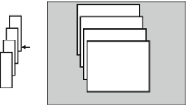
Fig. 4.13
Block diagram of RP-2
4.3.2
Power Domain and Partial Power-Off
Power-efficient SoC design for embedded applications requires several independent
power domains where the power of unused domains can be turned off. The power
domains were initially introduced to an SoC for mobile phones [
3
] , which de fi ned
20 hierarchical power domains, but most of the power domains were assigned to
peripheral IPs using low-leakage, high-Vt transistors. In contrast, high-performance
multicore SoCs use leaky low-Vt transistors for CPU cores, and reducing the leak-
age power of such cores is the primary goal. The RP-2 was developed for target use
in power-efficient, high-performance embedded applications. Sixteen power
domains were defined so that they can be independently powered off. A resume-
standby mode was also defined for fast resume operation, and the power levels of
the CPU and the URAM of a core are off and on, respectively. Each processor core
can operate at a different frequency or even dynamically stop the clock to maintain
processing performance while reducing the average operating power consumption.
Figure
4.14
illustrates the power domain structure of eight CPU cores with eight
URAMs. Each core is allocated to a separate power domain so that the power supply
can be cut off while unused. Two power domains (C
n
and U
n
, for
n
ranging from
0 to 7) are assigned to each core, where U
n
is allocated only for URAM. By keeping
the power of U
n
on, the CPU status is saved to URAM before the C
n
power is
turned off, and restored from URAM after C
n
power is turned on. This shortens the
restart time compared with a power-off mode in which both C
n
and U
n
are powered
off together. Each power domain is surrounded by power switches and controlled by
a power switch controller (VSWC).
Table
4.4
summarizes the power modes of each CPU. Light-sleep mode is suit-
able for dynamic power saving while cache coherency is maintained. In sleep mode,
almost all clocks for the CPU core are stopped. In resume-standby mode, the leak-
age current for eight cores is reduced to 22 mA from 162 mA in sleep mode, and
leakage power was reduced by 86%.


Search WWH ::

Custom Search