Global Positioning System Reference
In-Depth Information
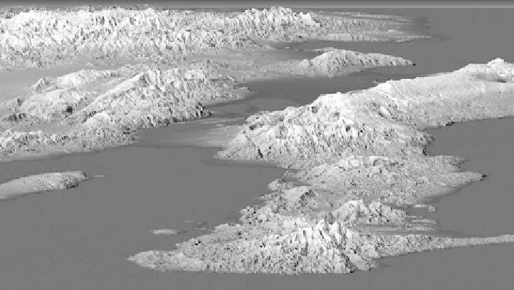
FIGURE 8.10.
A NASA X-band SAR radar image of Haiti, with 3-D rendering (vertical
scale exaggerated by a factor of 2). This image was taken before the devastating
earthquake of 2010; a linear fault line is evident in the center of the picture.
Image
courtesy of NASA/JPL/NGA.
radar equipment is smaller, more reliable, more capable, and easier to use
than at any time in the past. Additional equipment enhances radar naviga-
tion. Thus, the humble
corner reflector
attached to a marker buoy—placed
in a channel or harbor entrance, for example—reflects a signal back to a
radar receiver. Corner reflectors work as shown in figure 8.11. The equip-
ment is inexpensive, has no moving parts, and reflects a wide bandwidth of
transmitted frequencies.
By now you have a pretty good idea of how radar can enhance marine
navigation. Radar corner reflectors replace the lighthouses and other prom-
inent coastal features used in earlier times; a ship o√shore can obtain a
position fix from two bearings to reflectors of known position. Better: be-
cause radar provides an estimate of target range, a single reflector (marked
on a chart) will su≈ce to fix ship position via range and bearing. Another
technique is
tangent bearing
. Suppose that there is no reflector within the
operating range of your radar unit,
18
but you, cozily retired on your luxury
18. The e√ective operating range of a radar depends on many factors, such as transmit-
ted power, transmitter and receiver beamwidths, target size, and, perhaps most important
of all, the filtering and other processing that is applied to the received signal.