Biomedical Engineering Reference
In-Depth Information
17.5.3
Implementation
The delay-and-correlate algorithm is an improvement upon the Reichardt model and it is
adopted in the proposed motion detector design. The schematic block diagram including
two bR-pixels is shown in Figure 17.21. It uses temporal edges as the image features and
correlates them by using binary pulses (87). This binary pulse correlation significantly
increases motion detection robustness. Implementation can be divided into three separate
stages: feature extraction, pulse shaping, and direction/speed detection. To simplify pro-
totype development the bR photoreceptor array and its front-end circuitry are combined
with a microcontroller to realize the above three processing stages. The later two stages are
simulated by the microcontroller.
Spatiotemporal features of a moving object are typically extracted by applying edge
detectors to the input image. The differential responsivity of a bR photoreceptor allows a
simpler design to be realized. Use of unreliable temporal differentiation circuitry can be
avoided by combining each bR pixel with a switched integrator. The former transduces
light into electric signals and the latter transforms these signals into current pulses con-
taining edge information. Current pulses that are generated are then converted into volt-
age pulse using voltage comparators. An appropriate output trigger level is set according
to the minimum expected light power. Consequently, this threshold value determines the
contrast sensitivity of the motion detector. Generally, lower thresholds yield higher con-
trast sensitivity. When the bR pixel generates a sufficiently high signal, the comparator
will generate a corresponding pulse that is compatible with 5-V TTL circuitry.
The time delay within the motion detection algorithm is usually realized by pulse-shap-
ing circuitry. A delayed pulse is generated at the rising edge that is incoming from the pre-
vious stage. The duration of the delay is set long enough to allow the object to travel
between two neighboring pixels. A 4 MHz PIC16F684 microcontroller is used to simulate
the pulse shaping and direction/speed detection stages for four bR pixels. Four digital
input pins are used to sample the TTL signals from four pixel channels. Reading digital
R
1
R
2
Photoreceptors
Spatiotemporal
filters
Temporal delay
filters
Signal multipliers
-
+
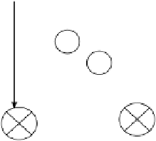
FIGURE 17.21
Block diagram of Reichardt's correlation model for
motion detection. The dashed boxes indicate the func-
tions that are accomplished by bR photoreceptors.
Difference operator
G
Motion response (output)