Biomedical Engineering Reference
In-Depth Information
(a)
(b)
150
µ
m
50
µ
m
(c)
(d)
C
2
H
4
C
2
H
4
Iron pattern
Porous Si
Si
75.
µ
m
15
µ
m
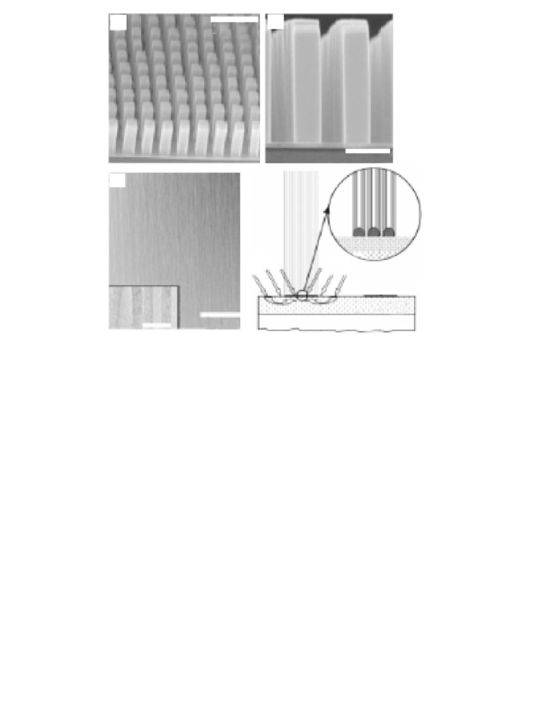
FIGURE 12.3
Self-oriented MWCNTs arrays grown by CVD on a catalytically patterned porous silicon substrate. (a) SEM
image of tower structures consisted of aligned nanotubes. (b) SEM image of the side view of the tower. (c) A
high-magnification SEM image showing aligned nanotubes in a tower. Inset: TEM image showing two
MWCNTs. (d) Schematic diagram of the growth process. (From Fan, S., Chapline, M., Franklin, N., Tombler, T.,
Cassell, A., Dai, H. (1999). Self-Oriented Regular Arrays of Carbon Nanotubes and Their Field Emission
Properties.
Science
, 283, 512-514.)
the SWCNTs/catalyst weight ratio reaches 50,000%. They found that the activity and the
lifetime of the catalyst could be enhanced by water. This approach represents a significant
advance toward the realization of large-scale and highly pure SWNT material.
12.2.3
Growth Mechanisms and Structure Control
The unique mechanical and electrical properties of CNTs are directly associated with their
structure, including their diameter, number of shells, and helicity. A thorough understand-
ing of the formation mechanisms for these nanotubular carbon systems is critical to design
procedures for controlling the growth conditions to obtain more practical structures, which
might be directly available for nanotechnology including biosensors.
It has been generally accepted that the growth mechanisms of both SWCNTs and
MWCNTs in the CVD process can be divided into two distinct classes: base-growth and
tip-growth [18]. In the base-growth mode, the catalyst particle remains on the support
surface and the nanotube elongates while maintaining a closed-end. In the tip-growth
mode, the catalyst particle is lifted off the support surface by the growing nanotube and
carried along at the tube end. The operation of these two modes depends on the