Information Technology Reference
In-Depth Information
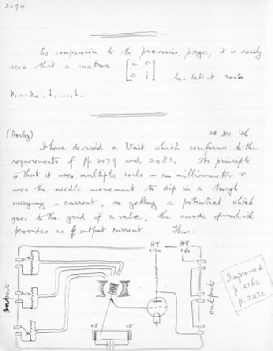
Figure 4.3.
page from ashby's journal, including his first sketch of the homeo-
stat wiring diagram. source: journal entry dated 28 december 1946 (p. 2094). (by
permission of jill ashby, sally bannister, and ruth pettit.)
curved Perspex dish at the front of figure 4.4b, the arc at the top of figure 4.4c.
As indicated in figure 4.4c, an electrical potential was maintained across this
trough, so that the tip of the vane picked up a voltage dependent on its posi-
tion, and this voltage then controlled the potential of the grid of a triode valve
(unlabeled: the collection of elements enclosed in a circle just below and to
the right of
M
in figure 4.4c; the grid is the vertical dashed line through the
circle), which, in turn, controlled the output currents.
Thus the input-output relations of the homeostat except for one further
layer of complication. As shown in figure 4.4c, each unit could operate in one
of two modes, according to the setting of the switches marked
S
, the lower
row of switches on the front of the homeostat's body in figure 4.4a. For one