Graphics Reference
In-Depth Information
input image, whose blue channel (b) has very low intensity on the person's left
face. (c) is the relighting result without using the constrained texture synthesis,
and (d) is relighting result with constrained texture synthesis. We can see that
almost all the unnatural color on the person's left face in (c) disappear in (d).
1.3 Implementation
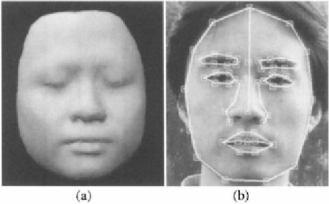
In our implementations, we use a cyberware-scanned face mesh as our
generic face geometry (shown in Figure 8.2(a)). All the examples reported
in this paper are produced with this mesh. Given a 2D image, to create the
correspondence between the vertices of the mesh and the 2D image, we first
create the correspondence between the feature points on the mesh and the 2D
image. The feature points on the 2D image are marked manually as shown in
Figure 8.2(b). We are working on automatically detecting these facial features
using techniques presented in [Hu et al., 2004]. We use image warping tech-
nique to generate the correspondence between the rest of the vertices on the
mesh and the 2D image. A mapping from the image pixels to a radiometrically
linear space is implemented to account for gamma correction. We have devel-
Figure 8.2.
(a): The generic mesh. (b): The feature points.
oped user interface for this face relighting software. It is illustrated in Figure 8.3.
interactive light editing. The panel on the right is a control panel for controlling
environment rotation, editing REM coefficients, and setting parameters such as
the coefficient for gamma correction.
The computation of the radiance environment map takes about one second
for a 640x480 input image on a PC with Pentium III 733 MHz and 512 MB
memory. The face relighting is currently implemented completely in software
without hardware acceleration. It runs about 10 frames per second.
Search WWH ::

Custom Search