Information Technology Reference
In-Depth Information
gate is constantly high, the level of the inducer molecule input
I
2
determines
the level of the repressor
R
3
.
R
3
is the input protein to the
R
3
/P
3
inverter
gate under study. The cyan fluorescent protein (CFP) transcribed along with
R
3
reports the level of the input signal, while the yellow fluorescent protein (YFP)
simultaneously reports the output signal expressed from the
R
3
/P
3
inverter.
The output of this circuit is the logical NOT of the inducer input signal.
A transfer function is the relation between the input signal and the output
signal of a gate or a circuit in steady state. Analog ranges represent digital
signals of zeros and ones. An ideal transfer curve for an inverter has an inverse
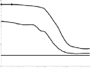
sigmoidal shape: the gain (or slope) is flat, then steep, then flat again. Because
of the gain, the output of the inverter is a better representation of the digital
value then the input (i.e., signal restoration). Figure 7.2 shows transfer curves of
three circuits with an inverter based on
cI
/
λ
P(R
−
O
12
)
. The flat curve represents
the nonresponsive behavior of a circuit with an inverter based on the original
cI
/
λ
P(R
−
O
12
)
genetic elements. This demonstrates that coupling genetic compo-
nents into a circuit without first understanding their device physics may yield
completely nonfunctional systems. Later in this section we describe genetic
mutations performed on the original
cI
/
λ
P(R
−
O
12
)
genetic elements to obtain a
functional circuit with the desired input/output behavior. Figure 7.2 shows how
two mutations result in an inverse sigmoidal transfer curve with good gain and
noise margins.
External Control of Signals
The first step in measuring the device physics of an inverter is to construct
genetic circuits that allow the researcher to externally set the
in vivo
level of
a signal. This is performed using circuits where an inverter is connected to an
1,000.00
operator
mutation
100.00
modified
RBS
10.00
1.00
0.1
1.0
10.0
100.0
1,000.0
IPTG (uM)
Figure 7.2
Genetic process engineering of the
cI
λ
P(R
−
O
12
)
inverter. A series of
genetic modifications converts a nonfunctional circuit into one that achieves the
desired input/output behavior.