Biomedical Engineering Reference
In-Depth Information
C
0
d
n
4
t
3
n
g
|
1
R
m
L
m
C
m
Figure 1.16
Electrical equivalent circuit for operation of a thickness shear mode
acoustic wave
sensor. Depicted are motional
resistance
(Rm),
inductance, (Lm), and circuit capacitances (Co and Cm).
d
n
3
.
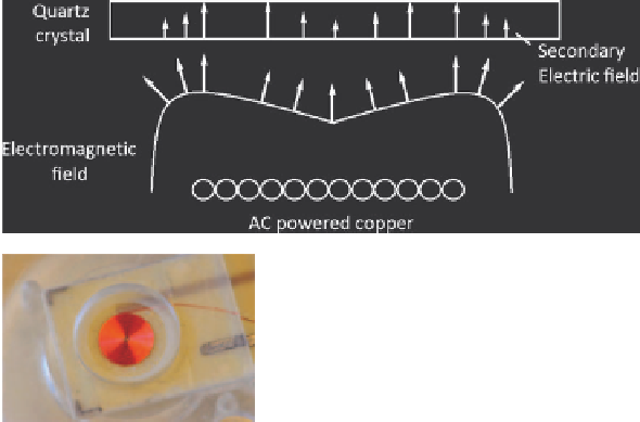
Figure 1.17
Electromagnetic acoustic wave sensor. Acoustic resonance is induced in
electrode free quartz by secondary electric field from flat-spiral coil.
mentioned above. There is also the possibility with this system of measuring the
frequency overtones of the device.
In terms of applications, recent years have seen a rapid increase in the
development of TSM technology which has been employed to detect surface-
induced protein conformational changes,
78
immunochemical interactions,
79
nucleic acid hybridization
80
and cell-surface attachment.
81
As mentioned
above, the major reason for these advances is that the response of the TSM in
liquids is extraordinarily sensitive to interfacial phenomena, which include
surface free energy, charge and viscosity effects.
A recent acoustic wave device development is the introduction of the
EMPAS structure.
82
In this technology, acoustic waves are instigated in an
electrode-less quartz wafer by an electromagnetic field generated in close
proximity to the wafer by a flat spiral coil (Figure 1.17). The secondary electric