Biomedical Engineering Reference
In-Depth Information
d
n
4
t
3
n
g
|
2
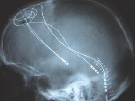
Figure 6.1
X-ray image of a deep brain stimulation electrode.
(Kindly provided by Russell J Andrews, MD, Smart Systems and Nano-
technology, NASA Ames Research Center.)
and has fewer side effects (not negligible though), such as dysarthria,
dysesthesia or cerebellar ataxia.
14
The brain pacemaker consists of a pulse generator, an electrode inserted in
the brain tissue and the connecting wire that is wrapped around the vagus nerve
in the neck (Figure 6.1).
The pulse generator is inserted into an opening in the chest or abdomen. The
neural pacemaker is destabilized in a controlled and coordinated manner,
usually with a first strong stimulus to reset the cluster of firing neurons,
followed by a weaker stimulus administered with a time delay that desyn-
chronizes the network by hitting the cluster in its most vulnerable phase. To
minimize local effects on the neural tissue, a deeper understanding of the
mechanisms taking place at molecular level still need to be achieved.
Minimizing energy consumption by optimizing signal intensities is also
essential, since the implanted pacemaker battery has a limited lifetime.
It is dicult to predict or to measure the effects of stimulation due to the
absence of parallel advances in the engineering design of the electrodes and a
scientific analysis of the technologies involved. It is now widely accepted that
the electric field depends on the shape of the electrodes, the distribution of
anodes and cathodes, and the biophysical properties of the tissue. The neural
response to the electric field is related to the second derivative of the potential
distributed along each neuron.
15,16
The therapeutic response to DBS is directly
linked to this axonal activation. Figure 6.2 shows the electrical model of the
axon, including the Ranvier nodes, the myelin attachment segments (MYSA),
the paranodal main segments (FLUT) and intermodal segments (STIN), the
fast (Na
f
) and persistent (Na
p
) sodium, slow potassium (K
s
) and linear leakage
(L
k
) conductances in parallel with the nodal capacitance (C
n
). G
m
in parallel
with C
m
represents the myelin sheath, and G
i
in parallel with C
i
represents the
intermodal axolemma.
n
3
.